Last Updated on May 14, 2025
Global Positioning System (GPS) helps us to find exact location by latitude and longitude coordinates. Couple of years back adding GPS functionality to microcontroller is a difficult task. But it is now become simple task due to the GPS hardware improvements. Here we are going to experiment simple Neo-6m GPS module Arduino interface. It will help us to learn about fetching GPS data and coordinates to the microcontroller and understanding how it works. We can develop this into embedded projects like wearable tracker, Drone location tracking, weather balloon tracking and real time location tracking etc.,
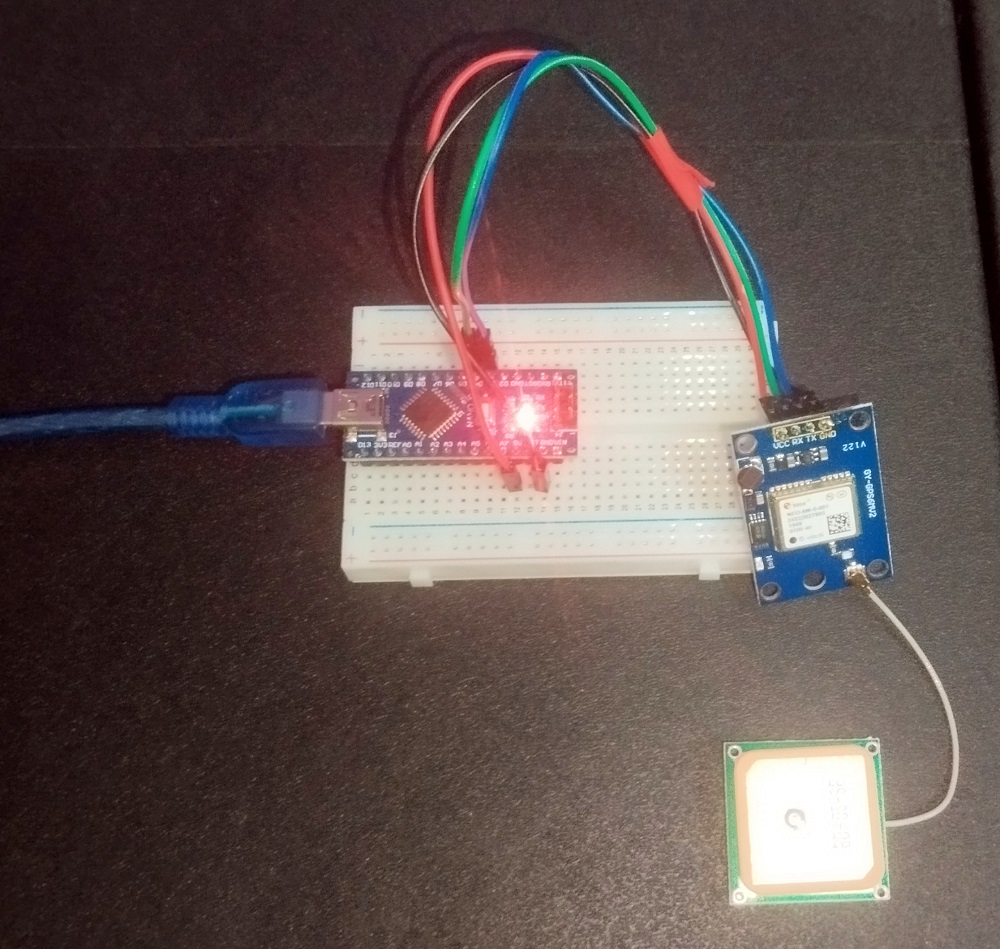
Here we used Arduino nano board and Neo-6m GPS module from ublox. Before connecting GPS module to your Arduino board check the Tx & Rx pins. wrong connection won’t bring output.
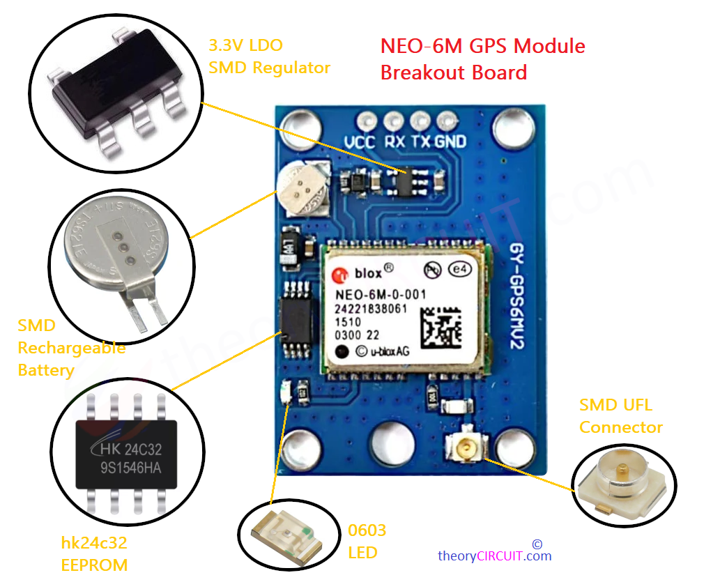
NEO-6M GPS Module
It is a high performance GPS Receiver module which is capable of tracking up to 22 satellites simultaneously. This module sends data through UART serial Interface (Tx & Rx). The output data will be in NMEA (National Marine Electronics Association) format. It contains Information like latitude, longitude, altitude, speed and UTC time. We will make Arduino code to print these details readable. Just look at the breakout board and its components.
Neo-6m works with power supply from 3.3V to 5V and hence it is suitable for most microcontroller. With -161dBm tracking sensitivity for reliable satellite acquisition, it will cold start as fast as 30 seconds and hot start in 1 second. It requires external antenna and should be face open sky for better results.
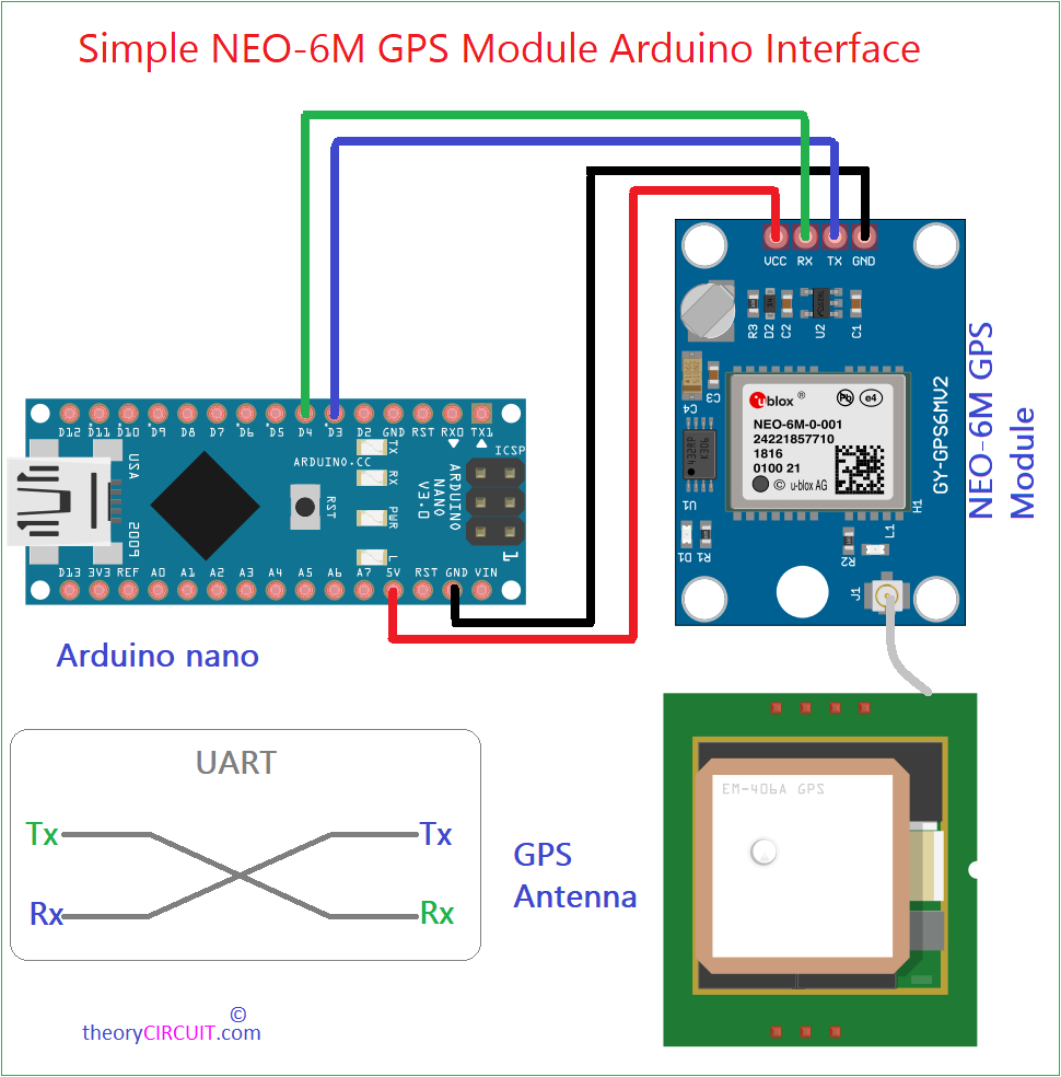
GPS Module Arduino Wiring Diagram
Components Required
- Arduino Board (here we used Arduino nano)
- NEO-6M GPS Module with external antenna
- Connecting Wires
- Bread board if required
- Computer with Arduino IDE for coding
Code Setup
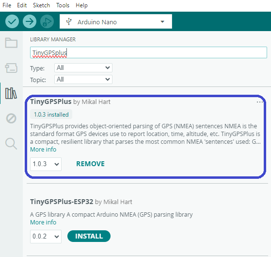
Install TinyGPSPlus library in Arduino IDE.
Wiring Table
| NEO-6M Pin | Arduino Nano Pin | Description |
|---|---|---|
| VCC | 5V or 3.3V | Power supply (NEO-6M supports 3.3V–5V; 5V is typically fine). |
| GND | GND | Common ground. |
| TX | D3 (or any digital pin) | Transmit pin (sends NMEA data to Arduino). |
| RX | D4 (or any digital pin) | Receive pin (not used in this setup, as Arduino sends no commands). |
After making wiring now connect Arduino board to the computer through USB and open Arduino IDE, then select exact board and port then upload the following code.
Arduino Code for GPS
/*code from theoryCIRCUIT.com */
#include <SoftwareSerial.h>
#include <TinyGPS++.h>

// Define GPS module connection pins
static const int RXPin = 4; // GPS TX -> Nano D4
static const int TXPin = 3; // GPS RX -> Nano D3
static const uint32_t GPSBaud = 9600;

// Create instances for GPS and serial communication
TinyGPSPlus gps;
SoftwareSerial gpsSerial(RXPin, TXPin);

void setup() {
  Serial.begin(9600);        // Initialize Serial Monitor
  gpsSerial.begin(GPSBaud);  // Initialize GPS module serial
  Serial.println("Initializing Neo-6M GPS with Arduino Nano...");
}

void loop() {
  // Feed data from GPS module to the GPS parser
  while (gpsSerial.available() > 0) {
    gps.encode(gpsSerial.read());

    if (gps.location.isUpdated()) {
      Serial.print("Latitude  : ");
      Serial.println(gps.location.lat(), 6);
      Serial.print("Longitude : ");
      Serial.println(gps.location.lng(), 6);
      Serial.print("Altitude  : ");
      Serial.print(gps.altitude.meters());
      Serial.println(" meters");
      Serial.print("Satellites: ");
      Serial.println(gps.satellites.value());
      Serial.print("Speed     : ");
      Serial.print(gps.speed.kmph());
      Serial.println(" km/h");
      Serial.println("------------------------------");
    }
  }
}
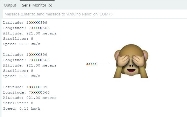
After successful uploading, the NEO-6M will cold start and requires up to one minute, depends on the open sky location and satellite signal availability this timing may vary. Before receiving GPS data the LED on Neo-6m board stays in OFF condition once the satellite signal received and locked by the GPS module then LED will blink at 1 Hz range. Also don’t forgot to use 9600 baud rate for obtaining good result.
Simple Prototype