
Last Updated on March 16, 2024
Rotary Encoders are useful for counting operations, it converts the angle of rotation to the counting digital signal, it can rotate 360º without any limits and gives pulse output. This article will give a basic Arduino Rotary Encoder Interfacing details and operation of conventional rotary encoders.
Rotary Encoder
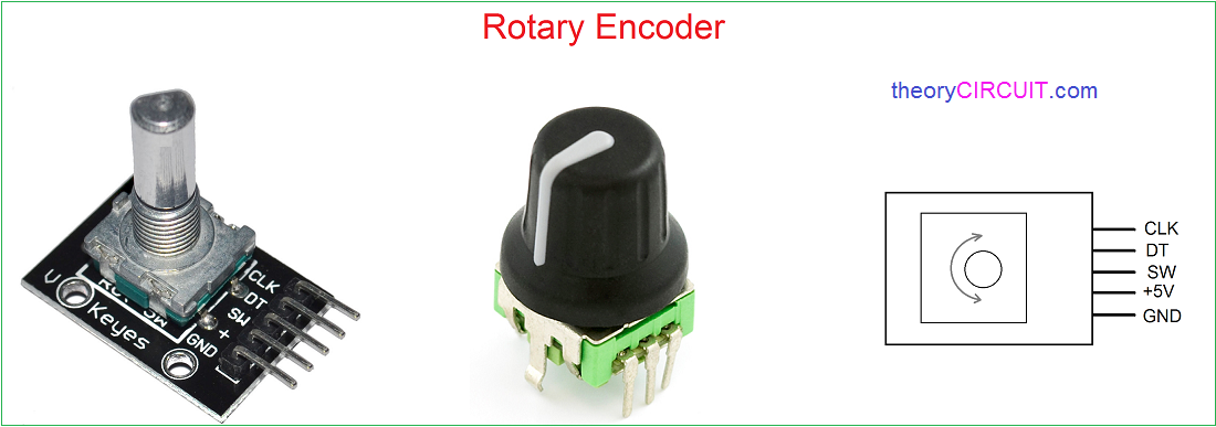
This rotary encoder breakout board has five pins,
- GND → Ground Supply
- + → +5V Power Supply
- SW → Button Switch
- DT → Encoder Pin B
- CLK → Encoder Pin A
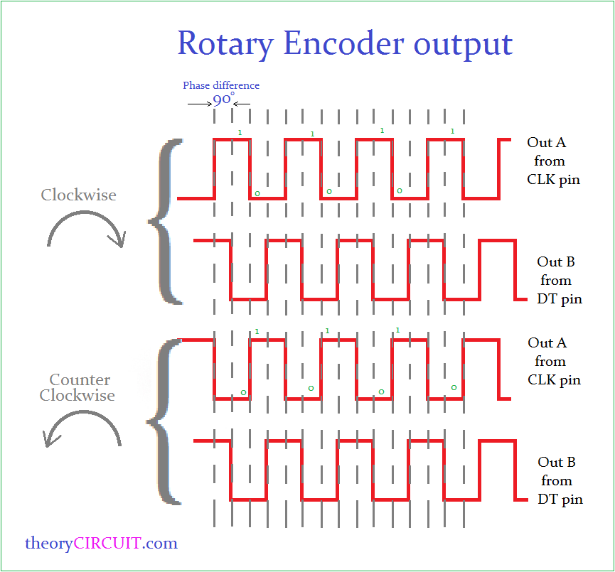
When the shaft is rotated in clock wise then the output pulse generated at encoder pin A with 90º out of phase from encoder pin B.
By the way when the shaft rotated in counter clock wise then the output generated at the encoder output pins A & B are inverted.
Rotary Encoder Arduino Interface
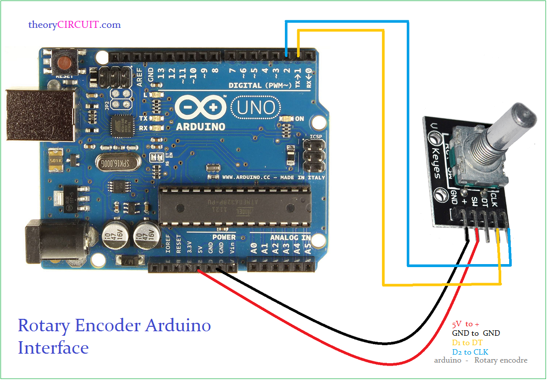
Connect the power supply pins of Rotary Encoder to Arduino board as + to 5V and Gnd to Gnd. Then connect CLK (Encoder out A) Pin to Arduino digital Pin D2 and DT (Encoder out B) pin to digital pin D1. After completing the hookup upload the following Sketch to get the angle and position of rotary encoder in serial monitor.
Arduino Sketch for Rotary Encoder
 #define encoderOutA 2 // CLK pin of Rotary Enocoder
 #define encoderOutB 1 // DT pin of Rotary Enocoder

 int counter = 0;
 int presentState;
 int previousState;
 void setup() {
   pinMode (encoderOutA,INPUT);
   pinMode (encoderOutB,INPUT);

   Serial.begin (9600);
      previousState = digitalRead(encoderOutA);   // Get current state of the encoderOutA
 }
 void loop() {
   presentState = digitalRead(encoderOutA);
      if (presentState != previousState)
      {
          if (digitalRead(encoderOutB) != presentState)
          {
       counter ++;
     }
     else {
       counter --;
     }
     Serial.print("Position: ");
     Serial.println(counter);
   }
   previousState = presentState; // Replace previous state of the encoderOutA with the current state
 }
In Arduino Code first define the output pins and initialize the count as 0, then declare the present & previous state variables. By using “IF” condition loop, get the present state of rotary encoder and compare with previous state. If there is no change then the count remains same, else the count value increases for clock wise rotation and decreases for counter clock wise rotation.