Last Updated on March 27, 2024
LA4440 Audio Amplifier Circuit designed with few external components and it can deliver 6 Watts + 6 Watts stereo output by using two 4Ω Loud speaker. This circuit biased with 12 Volt, 1 Amp power supply. IC LA4440 is a dual channel audio power amplifier integrated circuit designed for high quality stereo applications. Manufactured by Sanyo, this IC has gained popularity for its efficiency and versatility, making it a preferred choice for audio enthusiasts and professionals alike.
About LA4440
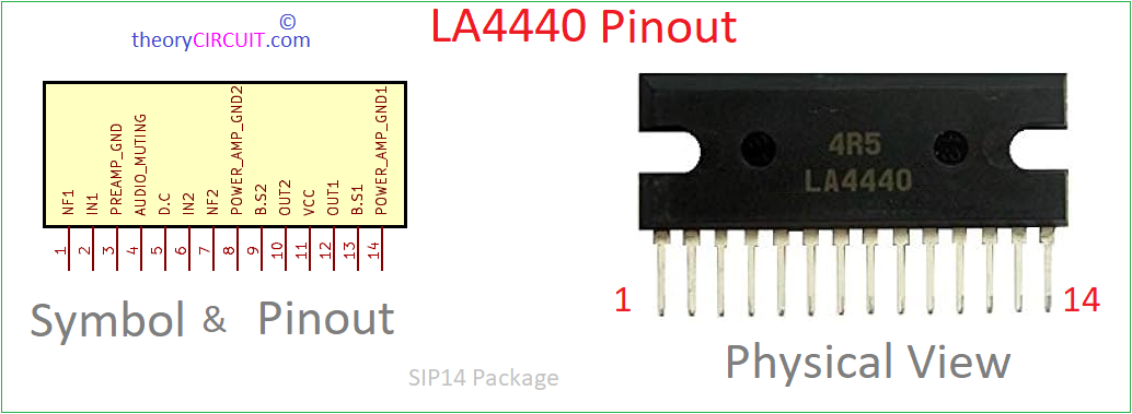
LA4440 IC capable of delivering 6W in two channel and 19W in Bridge type power Amplifier, It have good ripple rejection up to 46dB. This IC have Built in Thermal protector, Overvoltage & surge voltage protector and pin to pin short protector. It comes in SIP 14H package.
Power supply for Audio amplifier is very important, by providing proper bias we can ensure high efficiency, high gain. Here 12V/1A power supply given to LA4440 so that it exhibits low distortion and high fidelity audio reproduction. Wide frequency response ranging from 20Hz to 20KHz makes this IC suitable for broad spectrum of audio applications.
Circuit Diagram
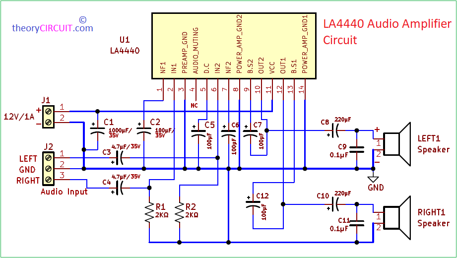
4440 ic amplifier circuit diagram
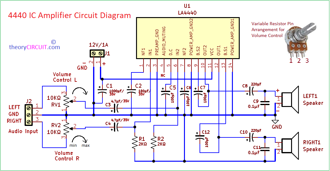
4440 IC Amplifier Circuit Diagram with volume control.
Components Required
| 1 | C5, C6, C7, C12 | 100μF/35V | CP_Radial_D8.0mm_P3.50mm | 4 | ||
| 2 | C3, C4 | 4.7μF/35V | CP_Radial_D4.0mm_P2.00mm | 2 | ||
| 3 | C8, C10 | 220μF/35V | CP_Radial_D8.0mm_P3.50mm | 2 | ||
| 4 | C9, C11 | 0.1μF | C_Disc_D3.0mm_W1.6mm_P2.50mm | 2 | ||
| 5 | C1 | 1000μF/35V | CP_Radial_D8.0mm_P3.50mm | 1 | ||
| 6 | C2 | 100μF/35V | CP_Radial_D8.0mm_P3.50mm | 1 | ||
| 7 | R1, R2 | 2KΩ | R_Axial_DIN0309_L9.0mm_D3.2mm_P12.70mm_Horizontal | 2 | ||
| 8 | U1 | LA4440 | SIP460W60P254L3690H1500Q14 | 1 | ||
| 9 | LEFT1, RIGHT1 | Speaker | TerminalBlock_bornier-2_P5.08mm | 2 | ||
| 10 | J1 | 12V/1A | TerminalBlock_Altech_AK300-2_P5.00mm | 1 | ||
| 11 | J2 | Screw_Terminal_01x03 | TerminalBlock_Altech_AK300-3_P5.00mm | 1 |
Construction & Working
This IC Requires only External Capacitors for its operation, Resistors R1 and R2 provides ground balance to the LEF and RIGHT audio input. This circuit don’t have Volume control, if you need one then introduce two variable Resistors in Audio Input. All capacitors used in this circuit are electrolytic capacitors with 35V Voltage ratings. VCC pin (11) is connected to the +12V power supply and Ground (-) supply is connected to the Pins (3, 8, 14). For bias filtering purpose C1 is connected across the +12V and GND line.
Audio Input LEFT is connected to the IN2 Pin (6) through 4.7µF C3 capacitor. RIGHT is connected to the the IN1 Pin (2) through 4.7µF C4 capacitor. OUT2 pin (10) is connected to the LEFT speaker and OUT1 pin (12) is connected to the RIGHT speaker through 220µF Capacitor. For noise filtering 0.1µF Capacitor is connected across the terminals of Loud speaker.
Now by applying bias and voice audio input we can hear the 6W+6W Amplified audio output from two loud speakers.
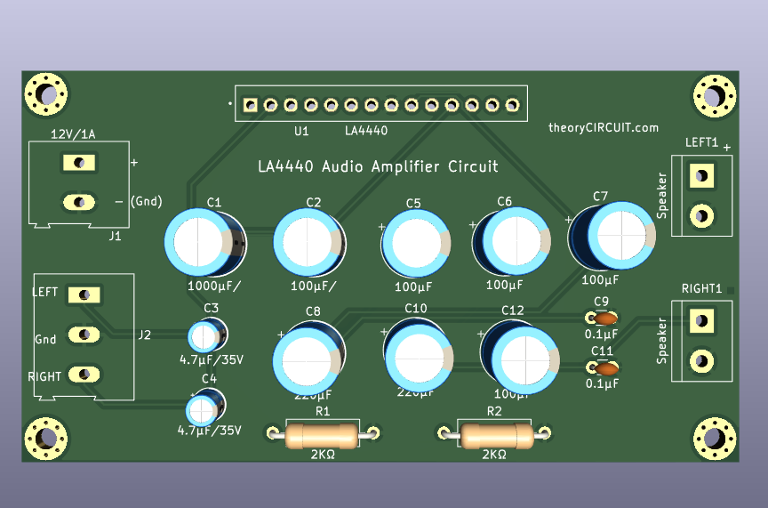
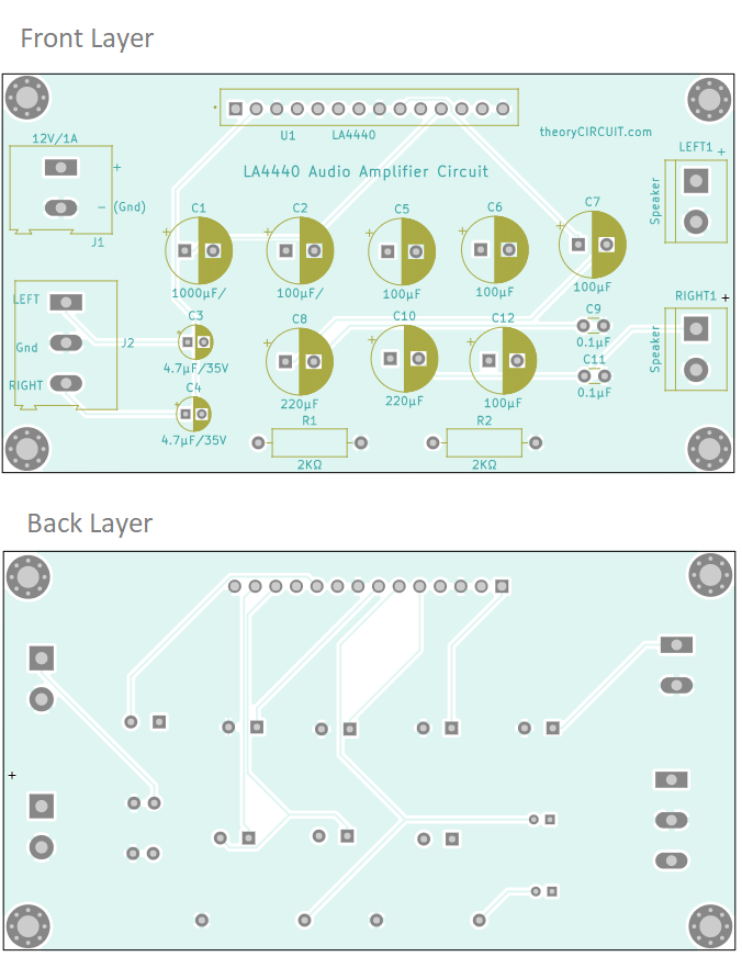
Printed Circuit Board
LA4440 Audio Amplifier Circuit PCB Gerber File.
Interactive Board Viewer


LA4440 Audio Amplifier Circuit PCB 3D View