
Last Updated on March 16, 2024
If you are an Electronic Engineer, Student or Hobyist then i don’t need to tell you about the Important role of Lab power supply, we refer it in different names like Regulated Power supply, Bench top power supply, Laboratary power supply but the operations are same, It is to provide Some Voltage and Current. When you are in the begining of setting up your own electronic prototype lab or something, the first primary tool is power supply, there are different types of power supply tools available in the market but with overpriced tag. Here is the Simple Lab Power Supply Circuit with Voltage and Current control for your basic tinkering need.
For efficient Prototyping, Safety and Protection we need a good reliable Lab Power supply, here is the Minimum Requirements for to design a Lab power supply.
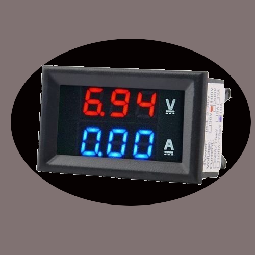
1. The ability to vary the output voltage to accommodate different circuit requirements. 2. A feature that allows you to set a maximum current limit, preventing damage to components in case of a short circuit. 3. A stable output with minimal electrical noise ensures accurate testing and reliable results. 4. Built in protection mechanisms that automatically shut down the power supply in case of overvoltage or excessive current. 5. A clear and accurate display indicating the output voltage and current, aiding in precise adjustments. Here we can use voltage current display module for Indicating the V and I.
Circuit Diagram

Components List
- Stepdown Transformer 220V to 15V AC
- Bridge Rectifier Module W10M
- Low Dropout Regulator LT3080 ( T PACKAGE, 5-LEAD PLASTIC TO-220) = 2
- Capacitor 220μF/16V, 10μF/16 = 2, 4.7μF/16V, 100μF/16V
- Resistor 1KΩ, 1Ω/2W
- Variable Resistor 100KΩ, 1MΩ
- LED 5mm Green
- Screw Terminal 2 pin
Construction & Working
About LT3080
Main Component in this circuit is Adjustable Low Dropout Regulator LT3080 from Analog Devices. U1 Regulator is Controls the current and U2 Regulator Controls the Voltage. It is Designed by Linear Technology now part of Analog Devices, this integrated circuit offers exceptional features for Designing Voltage and Current regulation circuits. One of its standout characteristics is its low dropout voltage, typically hovering around 350mV at full load, enabling efficient regulation even when the input voltage is close to the desired output voltage. With a current capability of up to 1.1A, the LT3080 caters to a broad spectrum of electronic applications, from low power circuits to more demanding loads. The device allows users to finely tune the output voltage with an external resistor divider network, providing the flexibility needed for diverse project requirements. Its thermal performance is noteworthy, and when appropriately heatsinked, the LT3080 remains stable and reliable in various operating conditions. Furthermore, its built in current limit feature ensures the protection of connected circuits, Internal protection circuitry includes current limiting and thermal limiting. It can be used in wide input voltage range from 1.2V to 36V, and comes in five different packages, making it a versatile and robust choice for power supply applications. Refer datasheet for more.
Construction of this circuit is very simple, A stepdown transformer converts 220V AC supply input to 15V AC supply and Bridge Rectifier Module W10M Converts AC into DC supply, then filter capacitor C1 removes AC ripples in the Rectifier DC supply, here 15V/1A DC supply is given as the primary input to the lab power supply. LED indicates the presence of Input DC supply. U1 LT3080 Regulator employed as a Current Regulator with SET input from Variable Resistor RV1, by tuning RV1 We can control the output current from 0 Amps to 1 Amps. U2 LT3080 Regulator employed as a Voltage Regulator with SET input from RV2 variable resistor, by tuning RV2 we can control the output Voltage from 0 Volt to 10 Volt. C4 and C5 capacitors performs filtering operation at the output end. We can modify this same circuit to give output up to 30 Volt / 1 Amps. by changing the input voltage range and Variable Resistor connected with SET pin.