
Last Updated on March 16, 2024
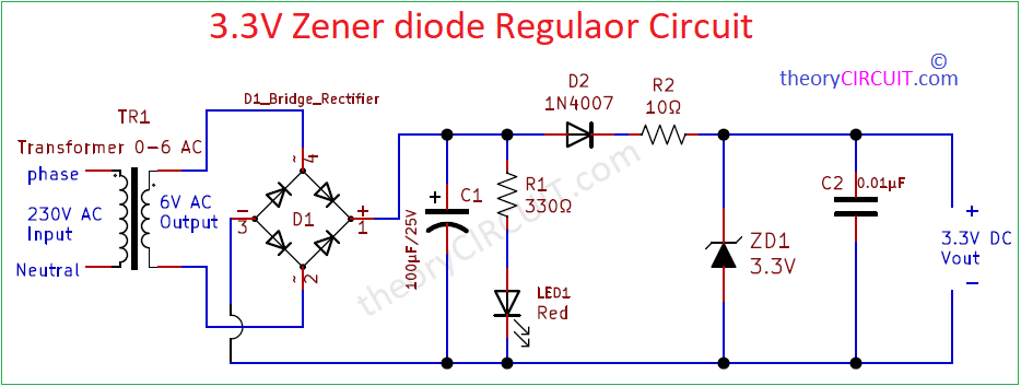
Simple 3.3V Zener diode Regulator Circuit designed to deliver Regulated 3.3V DC Supply with Output current up to 100 mA. If you want to obtain high Current output then you can use LDO Voltage Regulators. Here 3.3V DC supply obtained from 230V AC mains supply, as we know in order to reduce the Amplitude of AC supply we use stepdown transformer, here 0-6V AC output stepdown transformer used, then 6V AC supply converted in to DC supply by using bridge Rectifier module.
Instead of Bridge Rectifier module you can use Four 1N4007 diode in bridge Rectifier form. 6 Volt DC from the bridge Rectifier module may have some AC ripples, to remove those ripples in this circuit we use electrolytic capacitor C1 across the positive and negative terminal.
Circuit Diagram
Components Required (BOM)
| S.No | Designator | Value | Part Number | Quantity |
| 1 | TR1 | 230V to 0-6V AC | 0-6V Stepdown Transformer | 1 |
| 2 | C1 C2 | 100µF/25V 0.01µF | Electrolytic Disc capacitor | 1 1 |
| 3 | R1 R2 | 330Ω/0.5W 10Ω/0.5W | – – | 1 1 |
| 4 | D1 | – | Bridge Rectifier Module | 1 |
| 5 | LED1 | Red | – | 1 |
| 6 | ZD1 | 3.3V | Zener Diode | 1 |
| 7 | D2 | 1N4007 | Diode | 1 |
Construction & Working
This 3.3V Zener diode Voltage Regulator circuit built to work as standalone power source. Hence the continuous 6V AC supply Rectified into DC and filtered, LED 1 indicates the presence of input DC voltage to the Zener diode.
Diode D2 1N4007 blocks Reverse current flow, 3.3V ZD1 Zener diode connected parallel to the positive and negative supply in reverse bias after filter setup. When the DC supply input to the zener diode reaches 3.3V then zener break down occurs in Reverse bias and only allows 3.3V to the output. C2 Capacitor acts as filter element.
What is Zener Diode? How Zener Diode Works? Refer previous Article.
3.3V Zener Diode Setup
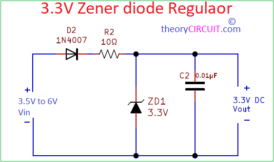
If you are available with DC Input Supply (3.5V to 6V) in your schematics then you can use the above circuit to Regulate and obtain 3.3V by using Zener Diode.
Update
3.7V Zener diode Regulator Circuit
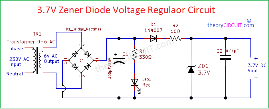
Operation of this 3.7V Zener diode Regulator Circuit is same as the previous circuit, Element ZD1 is 3.7V that is the only change and output of this circuit will be 3.7V DC.