
Last Updated on March 28, 2024
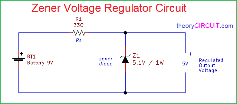
Simple Zener Diode Voltage Regulator Circuit designed to give 5 volt output from 9 volt input, you can replace the zener diode to get desired output voltage. For a simple voltage regulation in the circuit or design zerner diode is the cost effective solution.
We know zener diode is a two terminal active device and specially known for zener breakdown operation. A zener diode or Breakdown diode is a PN diode specially designed for operation in the breakdown region in the reverse bias condition. This diode operates in zener breakdown or avalanche breakdown, However the word zener is used for all components having sharp breakdown characteristics in reverse direction.
Zener Diode
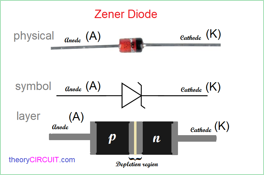
Zener diode has two terminals as Anode (A) and Cathode (K) and it is made of heavily doped P and N semiconductors these two regions creates depletion region at the junction. This zener diode is designed to operate at breakdown region during reverse bias.
V-I Characteristics of Zener diode
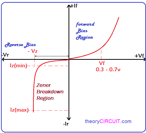
Here zener breakdown or avalanche breakdown occurs at reverse bias after reaching the breakdown point in terms of reverse voltage and current afterwards zener diode allows constant voltage with different current level.
Circuit Diagram
Available Zener Diodes
| 1/2W | 0.5W | 0.5W | 1W | 1W |
|---|---|---|---|---|
| Voltage | DO-35 | LL34 | DO-41 | LL41 |
| 2V0 | BZX55C2V0 | ZMM2V0 | ||
| 2V2 | BZX55C2V2 | ZMM2V2 | ||
| 2V4 | BZX55C2V4 | ZMM2V4 | ||
| 2V7 | BZX55C2V7 | ZMM2V7 | ||
| 3V0 | BZX55C3V0 | ZMM3V0 | 1N4727A | ZM4727A |
| 3V3 | BZX55C3V3 | ZMM3V3 | 1N4728A | ZM4728A |
| 3V6 | BZX55C3V6 | ZMM3V6 | 1N4729A | ZM4729A |
| 3V9 | BZX55C3V9 | ZMM3V9 | 1N4730A | ZM4730A |
| 4V3 | BZX55C4V3 | ZMM4V3 | 1N4731A | ZM4731A |
| 4V7 | BZX55C4V7 | ZMM4V7 | 1N4732A | ZM4732A |
| 5V1 | BZX55C5V1 | ZMM5V1 | 1N4733A | ZM4733A |
| 5V6 | BZX55C5V6 | ZMM5V6 | 1N4734A | ZM4734A |
| 6V2 | BZX55C6V2 | ZMM6V2 | 1N4735A | ZM4735A |
| 6V8 | BZX55C6V8 | ZMM6V8 | 1N4736A | ZM4736A |
| 7V5 | BZX55C7V5 | ZMM7V5 | 1N4737A | ZM4737A |
| 8V2 | BZX55C8v2 | ZMM8V2 | 1N4738A | ZM4738A |
| 9V1 | BZX55C9V1 | ZMM9V1 | 1N4739A | ZM4739A |
| 10V | BZX55C10V | ZMM10 | 1N4740A | ZM4740A |
| 11V | BZX55C11V | ZMM11 | 1N4741A | ZM4741A |
| 12V | BZX55C12V | ZMM12 | 1N4742A | ZM4742A |
| 13V | BZX55C13V | ZMM13 | 1N4743A | ZM4743A |
| 15V | BZX55C15V | ZMM15 | 1N4744A | ZM4744A |
| 16V | BZX55C16V | ZMM16 | 1N4745A | ZM4745A |
| 18V | BZX55C18V | ZMM18 | 1N4746A | ZM4746A |
| 20V | BZX55C20V | ZMM20 | 1N4747A | ZM4747A |
| 22V | BZX55C22V | ZMM22 | 1N4748A | ZM4748A |
| 24V | BZX55C24V | ZMM24 | 1N4749A | ZM4749A |
| 27V | BZX55C27V | ZMM27 | 1N4750A | ZM4750A |
| 30V | BZX55C30V | ZMM30 | 1N4751A | ZM4751A |
| 33V | BZX55C33V | ZMM33 | 1N4752A | ZM4752A |
| 36V | BZX55C36V | ZMM36 | 1N4753A | ZM4753A |
| 39V | BZX55C39V | ZMM39 | 1N4754A | ZM4754A |
| 43V | BZX55C43V | ZMM43 | 1N4755A | ZM4755A |
| 47V | BZX55C47V | ZMM47 | 1N4756A | ZM4756A |
| 51V | BZX55C51V | ZMM51 | 1N4757A | |
| 56V | BZX55C56V | ZMM56 | 1N4758A | |
| 62V | BZX55C62V | ZMM62 | 1N4759A | |
| 68V | BZX55C68V | ZMM68 | 1N4760A | |
| 75V | BZX55C75V | ZMM75 | 1N4761A |
You can use any of these zener diode as a Regulator in your design and put exact Rs Resistor according to the zerner diode and output voltage specifications.
In this schematic a 5.1 Volt zener diode is used in reverse bias, when the input voltage increase or above the zener breakdown then zener starts to conduct voltage up to the breakdown voltage level and gives regulated output voltage.
Sent me a zener diode voltage regulator in my email
Thanks for your Interest 🙂