
Last Updated on March 16, 2024
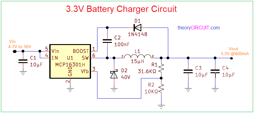
Here 3.3V Battery Charger Circuit designed by using MCP16301 from Microchip. The MCP16301 is highly integrated, high-efficiency, fixed frequency, step-down direct current (DC)- DC converter in a popular six-pin SOT-23 package that operates from input voltage sources upto 36V.
Integrated features include a high-side switch, fixed frequency peak current mode control, internal compensation, peak current limit, and over temperature protection. Minimal external components are necessary to develop a complete step-down DC-DC converter power supply.
Circuit Diagram
BOM
| S NO | DESIGNATOR | VALUE | QUANTITY |
| 1 | U1 | MCP16301 | 1 |
| 2 | C1,C3,C4 | 10μF | 1 |
| C2 | 100nF | 1 | |
| 3 | R1 | 31.6KΩ | 1 |
| R2 | 10KΩ | 1 | |
| 4 | D1 | 1N4148 | 1 |
| D2 | 40v | 1 | |
| 5 | L1 | 15μH | 1 |
Construction and Working
This Circuit example offers up to 96% efficiency with wide input voltage ranges (4.5V to 36V) and step-down to 3.3V at 600mA output. The output voltage is currently set at 3.3V and can be adjusted to a wide range from 2V to 15V. The integrated N-channel switch offers low RDSon at 460m . The MCP16301 load operation and efficiency with a fixed 5V output.
The EN pin 4 input is used to turn the device on and off. while turned off, only a few micro amps of current are consumed from the input for power shedding and load distribution application. The input is applied to pin 5, which is the input pin of an IC. pin2 is for the ground. pin1 is for the boost capacitor connection and the boost diode blocks the high voltage of the switch node from feeding back into the output voltage when the switch is turned on, forcing the switch node high. After these connection switch output is applied to the inductor and capacitor at the end . we get 3.3V at 600mA of current at the output.