
Last Updated on April 20, 2024
Crystal Oscillators are made from Quartz crystal and some times mixture of other substances like Tourmaline and Rochelle salt. We know when we apply energy to the crystal it produce vibrations at natural frequency and when we apply vibration it will produce small amount of energy.
This piezoelectric effect is makes Quartz crystals as unique element. This effect will help us to produce constant Oscillations. That’s why many electronic watches, Micro controllers, Micro processors, and Clock pulse requiring circuits uses the Crystal Oscillator. This article will help you to design crystal oscillator circuit and understand its operation.
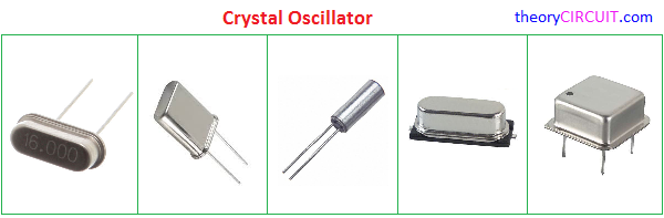
This Quartz Crystal material is produce constant oscillation at different temperature ranges, and it is naturally available so the quartz crystal is inexpensive. In crystal oscillator element quartz crystal is mounted between two metallic plates and terminals are bring out from these plates. Crystal oscillators are available in different frequency ranges and different sizes.
Crystal Equivalent circuit?
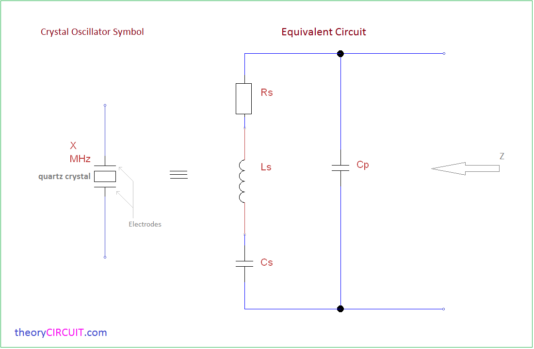
As we know the quartz crystal converts one type of energy into another energy hence it called as Transducer. Here Normal Crystal oscillator Symbol and its Equivalent circuit given.
Here equivalent circuit contains two segments one is to represent friction and stiffness of quartz crystal and another one is to represent parallel capacitance of plates. The series RLC circuit has Low valued Resistor Rs, A large valued Inductor Ls and A small valued Capacitor Cs and also parallel Capacitor Cp.
Series and Parallel Resonance
By using Crystal oscillator element we can create Series resonance oscillator or Parallel resonance oscillator, to obtain specific frequency from oscillators we need to calculate the resonant external components value.
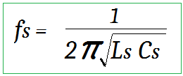
For Series Resonant frequency Fs the series Inductance Ls resonates with Series capacitance Cs and Crystal impedance will be the least one so the amount of feedback will be high.
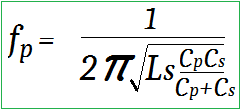
For Parallel Resonant frequency Fp the reactance of LsCs equals the reactance of Ls and parallel capacitor Cp (Cp resonate with Cs), and Crystal impedance will be highest and the feedback will the least.
Crystal Oscillator circuit diagram
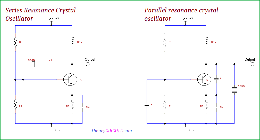
To construct the Series Resonance crystal oscillator place the crystal element and coupling capacitor between Collector and base terminals of common emitter configured circuit and we can obtain the oscillator output from collector terminal.
For Parallel Resonance crystal oscillator the crystal element is placed across the Collector and Emitter terminal and also the output is taken from collector terminal here the transistor is configured as common emitter.
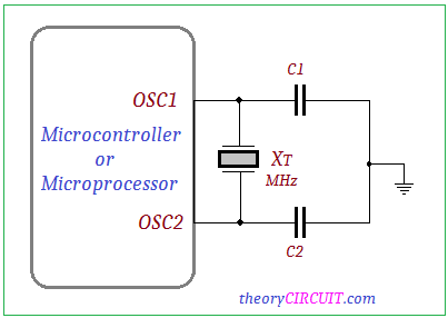
The switching components can be a transistor of FET or MOSFET, most Microcontrollers, Micro processors are provides external terminal to connect crystal element and there is no need for external oscillator circuit. Specific range of Crystal component is connected with Digital ICs.
Troubleshooting
Crystal device in the oscillator circuit may get damage due to the following reasons,
- Over Voltage
- Over Current
- Excessive Temperature
- Mechanical Stress
- Ageing
That’s why we have to test the crystal device before employing it in applications. Here the simple circuit to test the crystal device.
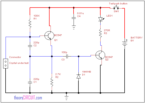
Read more about this circuit Here.