Last Updated on April 27, 2024
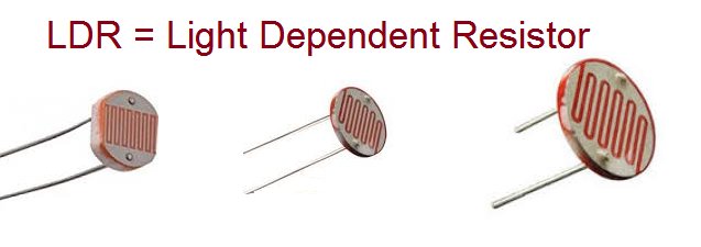
One of the simple and easy to use Resistance value based sensor is LDR (or) Photocell, this device will have two terminals and different size photo sensitive area like 3mm, 5mm, 10mm etc.., LDR stands for Light Dependent Resistor. It is a type of resistor device whose resistance changes depending on the amount of light falling on it. It is made of semiconductor materials called cadmium sulfide (CdS) which will have high Resistance. Cadmium atoms have 48 electrons so the outer band two electrons acts like free electrons and jumps to conduction band When light falls on the Cds material. It causing the conductivity to increase and thus reducing the resistance of the device. Conversely, So the LDR (or) Photocell (some times called as Photoresistor) will give High Resistance between its terminals when there is Low Light and Gives very Low Resistance when there is High Intensity Light. LDRs are commonly used in light sensing applications like streetlights, outdoor lighting systems, camera exposure control, and even in simple circuits like darkness detectors. Here we are going to make LDR Arduino Interfacing in three different methods.
LDRs or Photocell or Photoresistor…! can be made with Cadmium Sulfide (CdS), Cadmium Selenide (CdSe) , Indium Antimonide (InSb) or Lead Sulfide (PbS), depends on the material it will detect different wavelength lights and intensity level of light, most common LDRs are made with Cds semiconductor.
Due its passive characteristics it can be used in standalone circuits without microcontroller and it is capable of automate some light intensity based applications. Here is the few circuits to try.
- Automatic Darkness Detector Circuit
- Light Detector With Sensitivity Control Circuit
- LDR Switch Relay Circuit
LDR device can be easily interfaced with Microcontrollers, Arduino and Raspberry Pi boards as sensor and it can be used to control the output actuators with some level of conditions, let us start with measuring LDR value then control LED with some Range condition.
LDR Arduino Interfacing
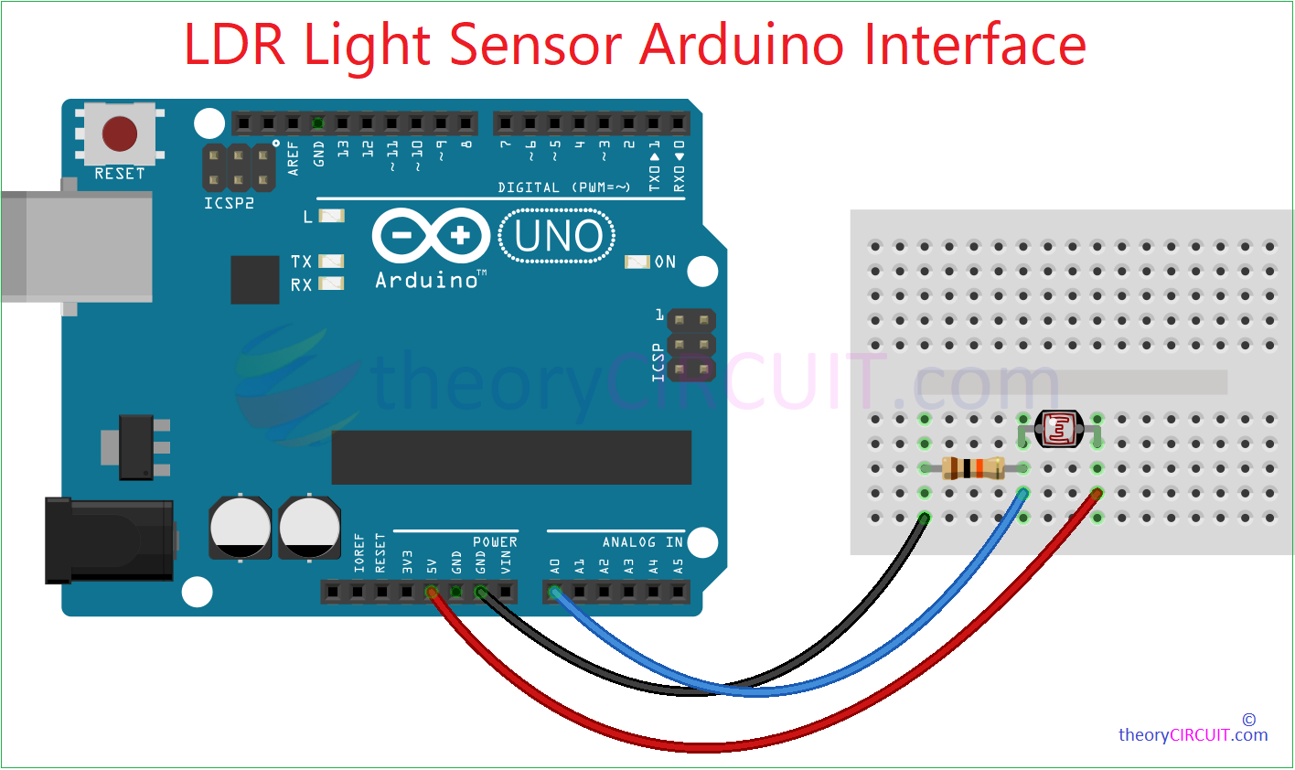
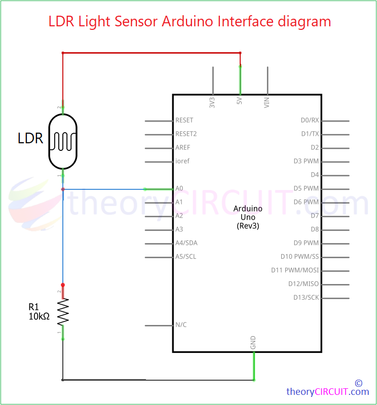
LDR Arduino Interfacing Circuit
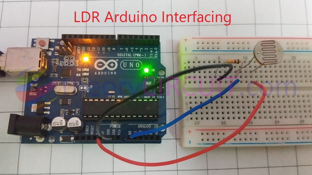
12mm LDR Connected with Arduino UNO Microcontroller Board
Components Required for LDR Arduino Interfacing
- Arduino Uno board (any type Arduino board)
- LDR
- Resistor 10KΩ, 220Ω each one
- LED 5mm Red
- Breadboard
- Arduino USB Cable A-Male to B-Male
- Computer with Arduino IDE
Video
Construction & Working
Here we are going to use our LDR as a Light sensor and to print value in serial monitor of Arduino IDE. LDR is a Resistance output device so we need to make a voltage divider setup to sense the varying voltage level due to light. One of the LDR terminal is connected to +5V and another terminal is connected with 10KΩ Resistor and this junction is connected to the A0 terminal of Arduino as sensor input. GND supply is connected with another terminal of 10KΩ Resistor, it forms voltage divider and the voltage between junction point and GND varies depends on the light falls on LDR.
Arduino code to read the LDR Value
// Define the analog pin for LDR
const int LDRpin = A0;

void setup() {
  // Initialize serial communication
  Serial.begin(9600);
}

void loop() {
  // Read the analog value from LDR
  int LDRvalue = analogRead(LDRpin);

  // Print the analog value to serial monitor
  Serial.print("LDR Value: ");
  Serial.println(LDRvalue);

  // Optional: You can add a delay to slow down the serial output
  delay(1000);
}
This code makes Arduino Pin A0 as input and it uses 10 bit analog to digital converter inside the Microcontroller chip ATmega328P and it map input voltage between 0 to 5V as integer values between 0 to 1023. See the video for output result.
Arduino LDR LED Interface
Here we are going to control an LED (you can use any output device with proper voltage level shifting) by using the LDR sensing value.
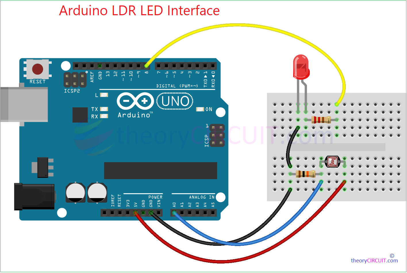
Arduino LDR LED Interface Circuit
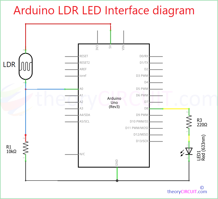
Wire Connections are same as previous one but the LED is connected with Arduino Digital Pin 8 through series Resistor 220Ω (Use this Series Resistor Value of LED Calculator. To decide the Resistor Value) – “Here the output voltage of Arduino digital pin is 5V and 5mm red led forward voltage is 2V and forward current is 15mA and considering tolerance 10% we get 220Ω” – We are going to write Arduino code with if condition to make LED ON and OFF.
Arduino LDR LED Interface Code
// Define the analog pin for LDR
const int LDRpin = A0;
void setup() {
  pinMode(8, OUTPUT); //LED Pin
  // Initialize serial communication
  Serial.begin(9600);
}

void loop() {
  // Read the analog value from LDR
  int LDRvalue = analogRead(LDRpin);

  // Print the analog value to serial monitor
  Serial.print("LDR Value: ");
  Serial.println(LDRvalue);

  // Optional: You can add a delay to slow down the serial output
  delay(300);

  //Connecting LED with condition
    if(LDRvalue<400)
   {
    digitalWrite(8,HIGH);
    Serial.println("LED ON");
   }
   else
   {
    digitalWrite(8,LOW);
    Serial.println("LED OFF");
   }
}
The above code makes LED ON if the LDR sensed value is below 400 and put LED OFF for other values.
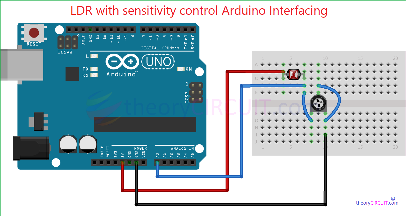
LDR with sensitivity control Arduino Interfacing
You can fix the Variable Resistor in LDR voltage Divider setup and make Changes in the Sensitivity level of LDR. This can be very helpful in projects that requires precision light intensity sensing.
LDR Arduino Schematic
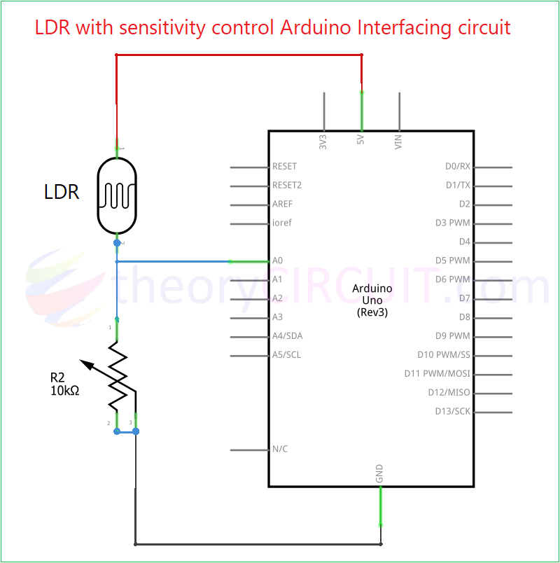
By varying the Resistor R2, we can pull down the output voltage and current through LDR and hence we can manipulate the sensitivity of LDR.
LDR with sensitivity control Arduino Interfacing Code
// Define the analog pin for LDR
const int LDRpin = A0;

void setup() {
  // Initialize serial communication
  Serial.begin(9600);
}

void loop() {
  // Read the analog value from LDR
  int LDRvalue = analogRead(LDRpin);

  // Print the analog value to serial monitor
  Serial.print("LDR Value: ");
  Serial.println(LDRvalue);

  // Optional: You can add a delay to slow down the serial output
  delay(1000);
}
See the sensitivity level changes for same intensity room light when we calibrate Variable Resistor in video.