Last Updated on March 26, 2024
LEDs and LED lighting devices are growing exponentially over the years and it revolutionized the lighting with their efficiency, color difference and durability. A LED (Light Emitting Diode) produce light through a process called electroluminescence, which is occurred during the recombine process between electron and hole in a semiconductor die. So the brightness or the intensity of emitting light (photons) depends on the current passing through LED device in forward bias. We know that LEDs are made with P-type, N-type Semiconductors with doping semiconductors like Gallium Arsenide (GaAs), Gallium Phosphide (GaP).., and forward conduction voltage of these semiconductors lies between 1.2 Volts to 3.5 Volts. So the Intensity of LED is depends on Current flow and that’s is why LEDs are called as Current controlled device.
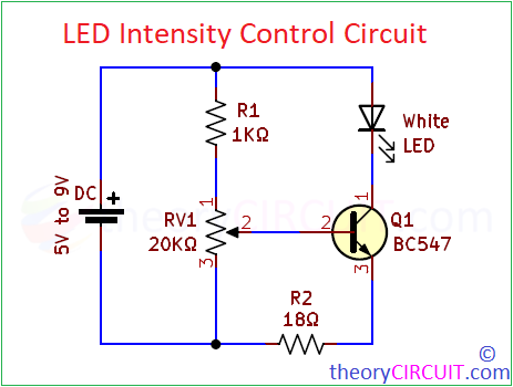
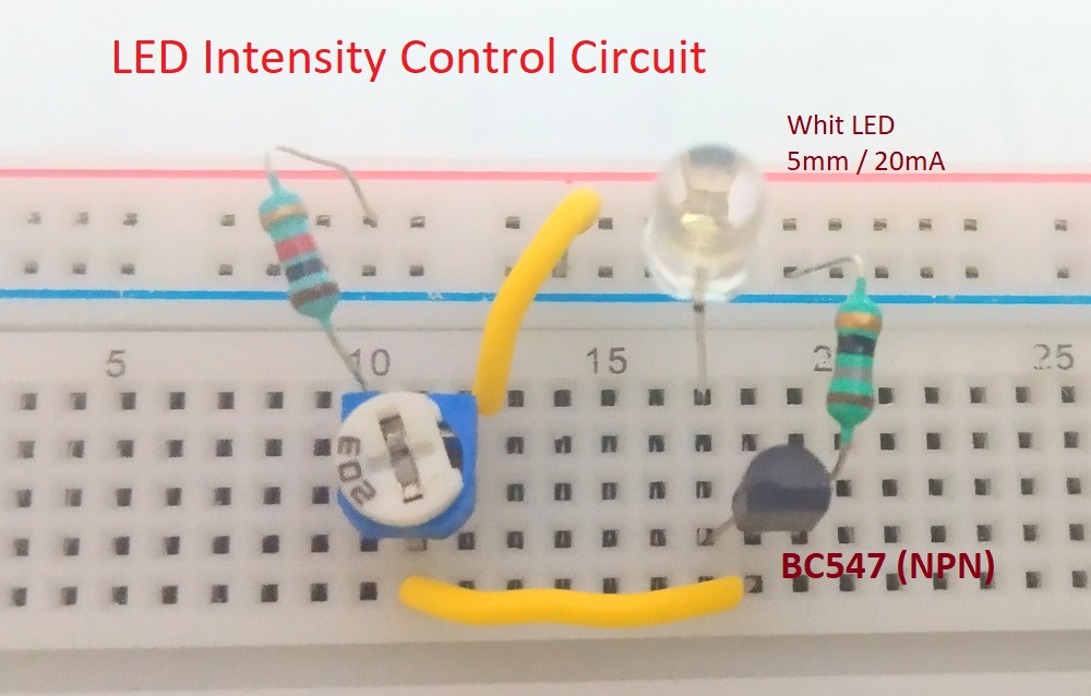
In this Article we are going to experiment LED Intensity Control Circuit with 5mm White LED and Transistor BC547. Here the Transistor BC547 (NPN) is configured in Common Emitter biasing and gets base Voltage from voltage divider setup made by R1 and RV1 Resistors. Depends on the Base-Emitter Voltage we can control the amount of current flow through collector to emitter terminal. By this way we can control the intensity and brightness of LED.
Circuit Diagram
Components List
- White LED 5mm
- Transistor BC547 (NPN)
- Resistor 1KΩ, 18Ω each one
- Variable Resistor 20KΩ
- DC power supply
- Wires
- Breadboard
Construction & Working
Construction of this circuit is very simple, first form voltage divider by using fixed value Resistor and Variable Resistor then connect the variable point to Transistor base then connect LED with the Collector terminal and use Emitter Resistor to dissipate over current flow through LED.
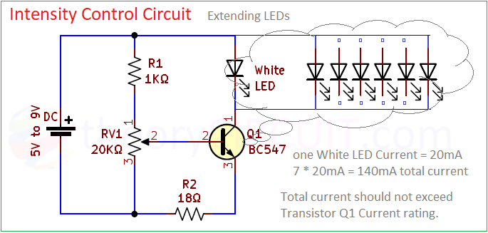
Here we have taken white LED which will approximately consume 15mA to 20mA current for maximum brightness, if you add more parallel LEDs then multiply its current consumption with numbers of LEDs. BC547 can handle up to 800mA collector to emitter current flow and it is more than enough for this experiment.
After completing hardware connection, lets turn on the power supply, here we have used 5V DC power supply and by increasing the RV1 value, output voltage through this voltage divider gets decrease and so the base voltage, hence very low current flows through Collector to Emitter terminal and collector connected LED feels very low current and produce very low intensity light.
When we decrease the RV1 value, output voltage from the divider gets increase and so the base voltage also increase, hence the transistor goes from saturation to active region and makes high current flow between Collector to Emitter terminal and the LED feels high current flow and hence produce high intensity light.