
Last Updated on March 17, 2024
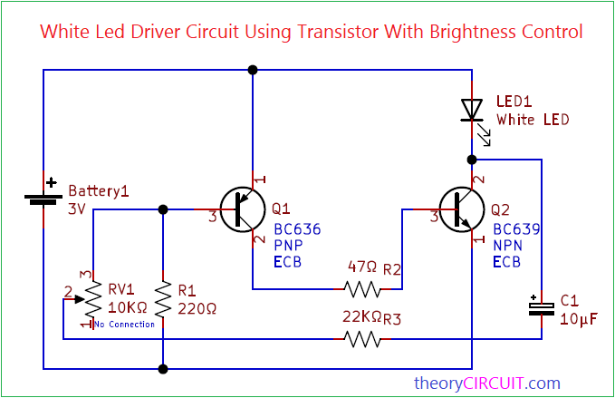
Simple White LED Driver Circuit Using Transistor With Brightness Control designed by using few easily available components. This circuit can be constructed in common PCB board in a Thump size formfactor and it can be useful in many ways. This circuit is designed to give PWM output by using two transistors and timing Resistor & Capacitor. You can use 1 watt white LED as a target load.
As we know Pulse Width Modulation (PWM) is a technique used to control the brightness of LEDs and other devices that can be turned on and off rapidly. PWM controls the average voltage or current supplied to the LED by adjusting the duty cycle of the on-off cycle. Here Q1, Q2 transistor with timing Resistor RV1 and timing capacitor C1 will produce PWM signal.
Circuit Diagram
Components Required
- Battery 3V
- Transistor Q1 BC636 PNP and Q2 BC639 NPN each one
- White LED
- Resistors R1 220Ω, R2 47Ω, R3 22KΩ
- Variable Resistor RV1 10KΩ
- Capacitor C1 10µF
Construction & Working
Q1 transistor collector terminal is connected to Q2 Transistor base and Timing elements C1, R3, RV1 are connected between Q2 collector and Q1 base terminals. LED is connected between +ve supply and Q2 collector terminal. When battery connected to this circuit C1 capacitor gets charge and discharge this cycle speed depends on the value of variable resistor RV1.
Depends on the Duty cycle percentage the LED will glow brighter or dimmer. If the PWM signal has a 75% duty cycle (ON for three-quarters of the time, OFF for one-quarter), the LED will be brighter than at 50% duty cycle but not as bright as if it were continuously ON. Or If the PWM signal has a 25% duty cycle (ON for one-quarter of the time, OFF for three-quarters), the LED will be dimmer.
Try This Circuit also
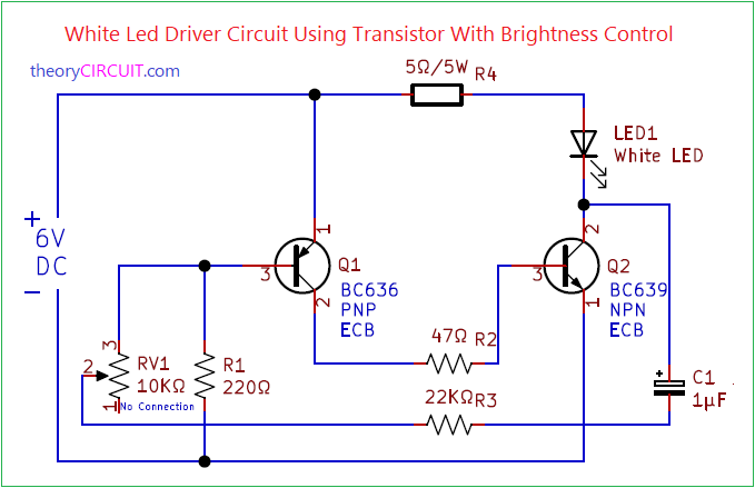
Operation of this circuit is same as the previous circuit but the operating voltage and current control resistor R4 and C1 values are changed to achieve higher brightness. You can add up to three white LEDs in series for this circuit.
Why R4 is needed so powerful?
It dissipates significant power as heat when the current flows through the LED and the transistors.