Last Updated on March 25, 2024
LED Dimmer Lights are very useful For Indication, Warning sign, and some lighting applications. To build this kind of circuit we don’t need expensive components. Here we have designed LED Dimmer Circuit using Timer IC 555 and BC547 Transistor. Of course it is very easy to construct and inexpensive way to bring dimming effect to LED lights. By using Power transistors and Addition external power supply we can control ‘n’ numbers of LEDs through this circuit.
Here Timer IC 555 Astable Multivibrator configuration is little modified with open Discharge pin (7) and open Control Voltage pin (5) to form as free relaxation oscillator which is depends on previous output signal through feedback.
IC 555 Pinout
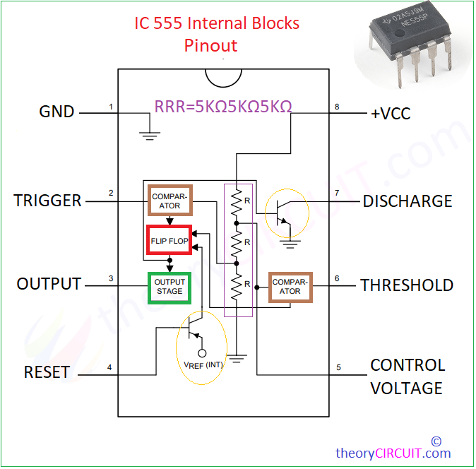
Timer IC 555 comes in different packages like DIP, SMD, SOIC8 and with different operating specifications, for general purpose we use NE555P and NE555L type ICs.
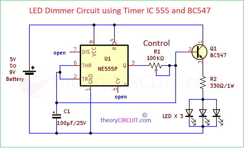
Circuit Diagram
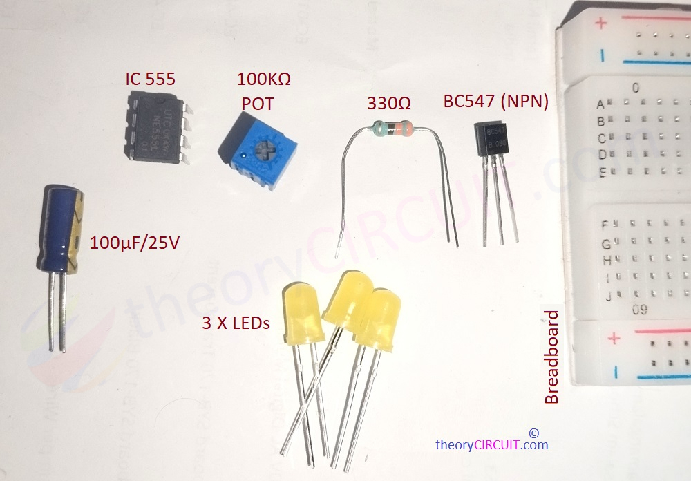
List of Components Required
- Timer IC 555
- Transistor BC547 (NPN)
- LED = 3 (Any color)
- Resistor 330Ω = 1
- Variable Resistor 100KΩ = 1
- Electrolytic Capacitor 100μF/25V = 1
- Breadboard
- Connecting Wires
- DC supply (5 to 9V)
Construction & Working
Here Timer IC configured in free running relaxation oscillator mode and we purposely removed Control voltage pin (it is used to decide the duty cycle of output pulse) and discharge pin, Timing Capacitor C1 is going to discharge through transistor Q1. Output pin is connected with Variable Resistor and to transistor base terminal, here a wire is makes feedback path between timing capacitor and output.
Transistor BC547 is configured in common emitter bias and whenever the voltage between base and emitter (VBE) rise above 0.7V then the transistor starts to conduct +V supply through collector to emitter. It makes LEDs glow. Due to Capacitor C1 the VBE voltage gets slowly rise and slowly decrease so that we get dimming effect in LED lights. Speed of charge and discharge of C1 can be adjust through Variable Resistor R1.