
Last Updated on April 23, 2025
Unlike Arduino, Interfacing I2C LCD with ESP32 using micropython code will take some extra effort but it worth a lot, because it will give more flexibility than the Arduino code, lets interface i2c 16X2 LCD with ESP32 board. Here you can learn to code ESP32 using micropython and Thonny IDE, if you are new to use MicroPython then read here to get started.
LCD?
Liquid Crystal Display shortly denoted as LCD, we can see different types of LCD everywhere. 16X2 LCD is a very common device being used in electronic projects and circuits. There are several options available in LCD display module, depends on our need we can choose it.
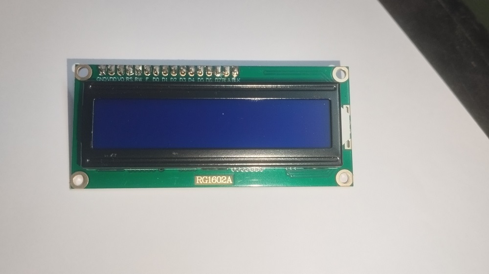
16X2 LCD is a common type of Alphanumeric display, it have 16 columns and 2 rows hence it can display 32 characters that is 16 per row. These displays are widely used in Embedded Systems, Microcontroller applications etc.., LCD display are available in different character, size, and color.
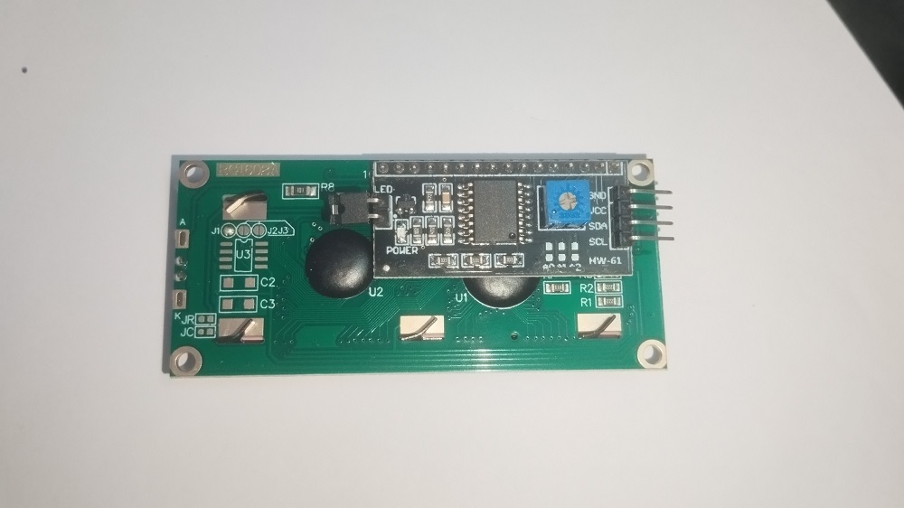
Standard 16X2 LCD will have 16 pins with Internal Controller called HD44780, some LCD will have different controller but operations are similar to the HD44780. To reduce the pin count and to save the gpio pins of microcontroller I2C modules are used with LCD displays.
16X2 LCD Interface Mode
- 4 bit mode – It uses 4 Data lines + Control lines
- 8 bit mode – It uses 8 data lines + Control lines
- I2C Interface – For I2C communication 16X2 LCD requires an I2C adapter module. It uses Power supply lines (Vcc, Gnd) and SDA, SCL lines.
Here we are going to Interface 16X2 LCD with ESP32 using I2C Interface mode.
16X2 LCD I2C Interface with ESP32
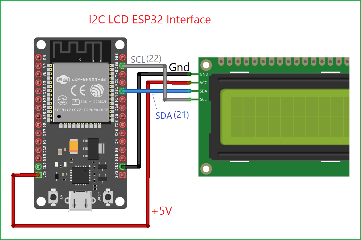
| 16X2 LCD Display | ESP32 Board |
| GND | GND |
| VCC | VIN (5V) or External PS with common GND |
| SDA | GPIO21 |
| SCL | GPIO22 |
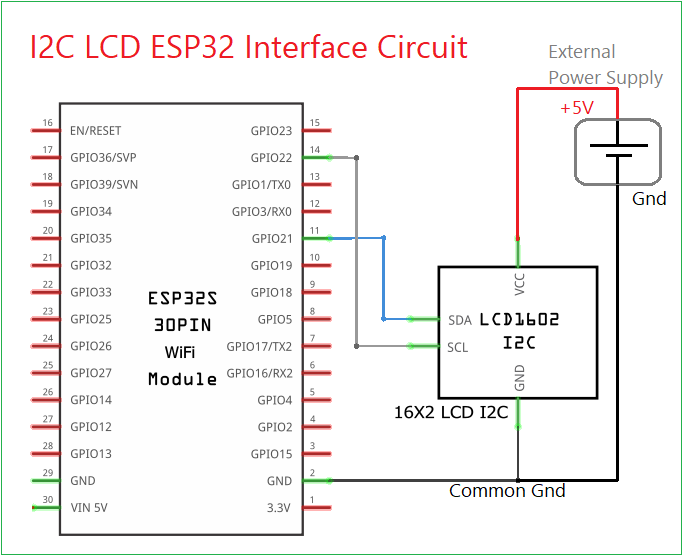
LCD display requires 5V Power Supply some may works fine with 3.3V but for bright output we need to bias LCD with 5V, If it is external power supply then make common GND (Ground) between external power supply and ESP32 GND pin. For i2c communication we need just 2 wires other than power supply. SDA (Serial Data) and SCL (Serial Clock) so that it is very easy to connect with microcontrollers I2C pins.
Wiring
Circuit Diagram
Components Required
- ESP32 Development Board (here DOIT Devkit V1)
- 16X2 LCD with I2C module
- Connecting Wires
- Computer with Thonny IDE
Working Video
Construction & Working
Connect I2C lines and power supply lines as mentioned in the circuit, If you are using external power supply for LCD (5V) then make common GND between power supply and ESP32 board, then only LCD display works properly. If not you will see just black box lines. For to upload the text display code to ESP32 and make 16X2 LCD to display text, we need following two LCD libraries in micropython device memory (ESP32 memory).
- i2c_lcd.py
- lcd_api.py
After saving these libraries in ESP32 memory, we can write main.py code to display text in LCD. Always name your code as “main.py” or “boot.py” for to run when the ESP32 powered ON. Saving in other names will be lost when power supply off.
Library i2c_lcd.py
Connect your ESP32 board with computer and make sure Thonny IDE shows the connected port number, Copy whole i2c_lcd.py code without missing single line (just select all + Copy) then open Thonny IDE, File > New > (paste Copied code then) Save > MicroPython Device > (Give file name exactly as ‘i2c_lcd.py’ then) > OK. Now you have saved one library.
# i2c_lcd.py code from theoryCIRCUIT

from lcd_api import LcdApi
from machine import I2C
import time

class I2cLcd(LcdApi):
    LCD_I2C_ADDR = 0x27
    LCD_WIDTH = 16
    LCD_CHR = 1
    LCD_CMD = 0
    LCD_BACKLIGHT = 0x08

    ENABLE = 0b00000100

    def __init__(self, i2c, i2c_addr, num_lines, num_columns):
        self.i2c = i2c
        self.i2c_addr = i2c_addr
        self.backlight = self.LCD_BACKLIGHT
        self.num_lines = num_lines
        self.num_columns = num_columns
        time.sleep_ms(20)
        self.hal_write_init_nibble(0x03)
        time.sleep_ms(5)
        self.hal_write_init_nibble(0x03)
        time.sleep_ms(1)
        self.hal_write_init_nibble(0x03)
        self.hal_write_init_nibble(0x02)
        cmd = self.LCD_FUNCTION | self.LCD_FUNCTION_2LINES
        self.hal_write_command(cmd)
        self.hal_write_command(self.LCD_ON_CTRL | self.LCD_ON_DISPLAY)
        self.hal_write_command(self.LCD_CLR)
        time.sleep_ms(2)
        self.hal_write_command(self.LCD_ENTRY_MODE | self.LCD_ENTRY_INC)

    def hal_write_init_nibble(self, nibble):
        byte = (nibble << 4) | self.backlight
        self.i2c.writeto(self.i2c_addr, bytes([byte | self.ENABLE]))
        self.i2c.writeto(self.i2c_addr, bytes([byte]))

    def hal_write_command(self, cmd):
        self.hal_write_byte(cmd, self.LCD_CMD)

    def hal_write_data(self, data):
        self.hal_write_byte(data, self.LCD_CHR)

    def hal_write_byte(self, data, mode):
        high = mode | (data & 0xF0) | self.backlight
        low = mode | ((data << 4) & 0xF0) | self.backlight
        self.i2c.writeto(self.i2c_addr, bytes([high | self.ENABLE]))
        self.i2c.writeto(self.i2c_addr, bytes([high]))
        self.i2c.writeto(self.i2c_addr, bytes([low | self.ENABLE]))
        self.i2c.writeto(self.i2c_addr, bytes([low]))

    def hal_sleep_ms(self, ms):
        time.sleep_ms(ms)
lcd_api.py
Copy whole lcd_api.py code without missing single line (just select all + Copy) then open Thonny IDE, File > New > (paste Copied code then) Save > MicroPython Device > (Give file name exactly as ‘lcd_api.py’ then) > OK. Now you have saved library and ready to write main.py code.
# lcd_api.py code from theoryCIRCUIT

class LcdApi:
    LCD_CLR = 0x01
    LCD_HOME = 0x02
    LCD_ENTRY_MODE = 0x04
    LCD_ENTRY_INC = 0x02
    LCD_ENTRY_SHIFT = 0x01
    LCD_ON_CTRL = 0x08
    LCD_ON_DISPLAY = 0x04
    LCD_ON_CURSOR = 0x02
    LCD_ON_BLINK = 0x01
    LCD_MOVE = 0x10
    LCD_MOVE_DISP = 0x08
    LCD_MOVE_RIGHT = 0x04
    LCD_FUNCTION = 0x20
    LCD_FUNCTION_2LINES = 0x08
    LCD_FUNCTION_5x10DOTS = 0x04
    LCD_FUNCTION_8BIT = 0x10
    LCD_CGRAM = 0x40
    LCD_DDRAM = 0x80

    def __init__(self, num_lines, num_columns):
        self.num_lines = num_lines
        if self.num_lines > 1:
            self.displayfunction = self.LCD_FUNCTION | self.LCD_FUNCTION_2LINES
        else:
            self.displayfunction = self.LCD_FUNCTION
        self.num_columns = num_columns
        self.cursor_x = 0
        self.cursor_y = 0

    def clear(self):
        self.hal_write_command(self.LCD_CLR)
        self.hal_sleep_ms(2)

    def home(self):
        self.hal_write_command(self.LCD_HOME)
        self.hal_sleep_ms(2)

    def set_cursor(self, col, row):
        self.cursor_x = col
        self.cursor_y = row
        addr = col & 0x3F
        if row & 1:
            addr += 0x40
        self.hal_write_command(self.LCD_DDRAM | addr)

    def write(self, s):
        for char in s:
            self.hal_write_data(ord(char))

    def putstr(self, string):
        self.write(string)

    def move_to(self, col, row):
        self.set_cursor(col, row)

    # Override in subclass
    def hal_write_command(self, cmd):
        pass

    def hal_write_data(self, data):
        pass

    def hal_sleep_ms(self, ms):
        pass
Static Text Display Code
To display static 2 line text on 16X2 LCD use the following code, you can edit the text “theoryCIRCUIT” and “Hello World” as you want. Remember to place only 16 characters per line.
# MicroPython Code to Display text in 16X2 I2C LCD using ESP32 board from theoryCIRCUIT
from machine import I2C, Pin
from time import sleep
from i2c_lcd import I2cLcd

# Define ESP32 I2C pins
i2c = I2C(0, scl=Pin(22), sda=Pin(21), freq=400000)

# Scan for I2C devices and print their addresses in decimal and hex
devices = i2c.scan()
if not devices:
    print("No I2C device found.")
    raise Exception("No I2C devices detected.")
else:
    print("I2C devices found:")
    for device in devices:
        print("  Decimal: {}, Hex: {}".format(device, hex(device)))

# Assume the first found address is the LCD
lcd_addr = devices[0]
print("Using LCD at I2C address:", hex(lcd_addr))

# Initialize the LCD
lcd = I2cLcd(i2c, lcd_addr, 2, 16)  # 2 rows, 16 columns

# Clear display and print messages
lcd.clear()
lcd.move_to(0, 0)
lcd.putstr("theoryCIRCUIT")

lcd.move_to(0, 1)
lcd.putstr("Hello World")
Code Explanation
First step is to import the libraries, here the lcd_api.py library works behind as a Application Programming Interface, for controlling characters in LCD, Cursor movement, Clearing the screen, text display.
# MicroPython Code to Display text in 16X2 I2C LCD using ESP32 board from theoryCIRCUIT
from machine import I2C, Pin
from time import sleep
from i2c_lcd import I2cLcd
Autodetecting I2C Address
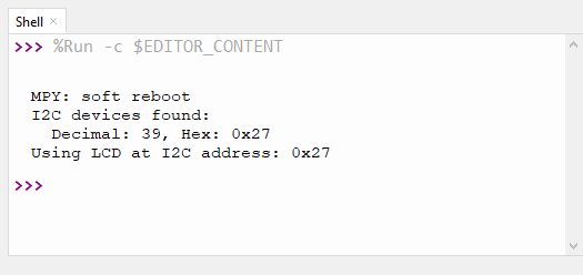
To detect I2C Address of connected devices in the ESP32, we have used the following code, by detecting it, the code places exact address of I2C line for further operation and display address in the shell. If there is no device found then it will show “No device found” message.
# Scan for I2C devices and print their addresses in decimal and hex
devices = i2c.scan()
if not devices:
    print("No I2C device found.")
    raise Exception("No I2C devices detected.")
else:
    print("I2C devices found:")
    for device in devices:
        print("  Decimal: {}, Hex: {}".format(device, hex(device)))
Initialize the LCD
# Initialize the LCD
lcd = I2cLcd(i2c, lcd_addr, 2, 16)  # 2 rows, 16 columns
Declaring 2 rows and 16 columns of LCD.
Instructions for LCD Display
To clear all the displayed characters lcd.clear()
To move the cursor lcd.move_to(0, 0), that is lcd.move_to(character number 0 to 15, row number 0 to 1)
To send text (string) to the LCD, lcd.putstr(“text”)
Tuning
If your LCD won’t display anything after everything done right, just adjust the potentiometer in the I2C display driver either in forward or backward then you will see the changes in the contrast and firmly you can adjust to make clear visibility.
Displaying Special Characters
To display Special Character in the LCD you need either binary sequence or hex code for your character, you can make Special Character (symbol) and binary code here: https://theorycircuit.github.io/Interactive-LCD-Custom-Character-Generator/
from machine import I2C, Pin
from time import sleep
from i2c_lcd import I2cLcd

# Define I2C interface (ESP32 default pins)
i2c = I2C(0, scl=Pin(22), sda=Pin(21), freq=400000)

# Scan for I2C devices and print address
devices = i2c.scan()
if not devices:
    raise Exception("No I2C device found.")
else:
    for dev in devices:
        print("I2C device found at decimal:", dev, "hex:", hex(dev))

# Use first found I2C address
lcd_addr = devices[0]
lcd = I2cLcd(i2c, lcd_addr, 2, 16)  # 2 rows, 16 columns

# Define heart symbol (5x8)
heart = bytearray([
    0b00000,
    0b01010,
    0b11111,
    0b11111,
    0b11111,
    0b01110,
    0b00100,
    0b00000
])

# Function to load custom char to CGRAM slot
def load_custom_char(lcd, location, charmap):
    location &= 0x07  # slots 0–7 only
    lcd.hal_write_command(0x40 | (location << 3))  # CGRAM set command
    for byte in charmap:
        lcd.hal_write_data(byte)

# Load the heart to CGRAM slot 0
load_custom_char(lcd, 0, heart)

# Display heart on LCD
lcd.clear()
lcd.move_to(5, 0)        # Row 0, Column 5
lcd.putstr(chr(0))       # Display custom char from CGRAM slot 0

# Optional: add message
lcd.move_to(0, 1)
lcd.putstr("theoryCIRCUIT")