Last Updated on March 16, 2024
The flex sensor also a variable resistor but the Resistance of this sensor changes according to the bending (flexing). It contains carbon on a strip of plastic to act like a variable resistor.
The flex sensor can be used for servo motor control, intensity control or you can use where ever the resistance need to be changed when the bending occurs. Here the circuit constructed with arduino and LED, when the flex sensor bends the intensity of LED changes accordingly.
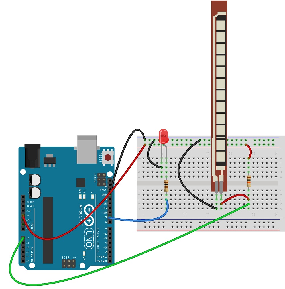
Circuit diagram
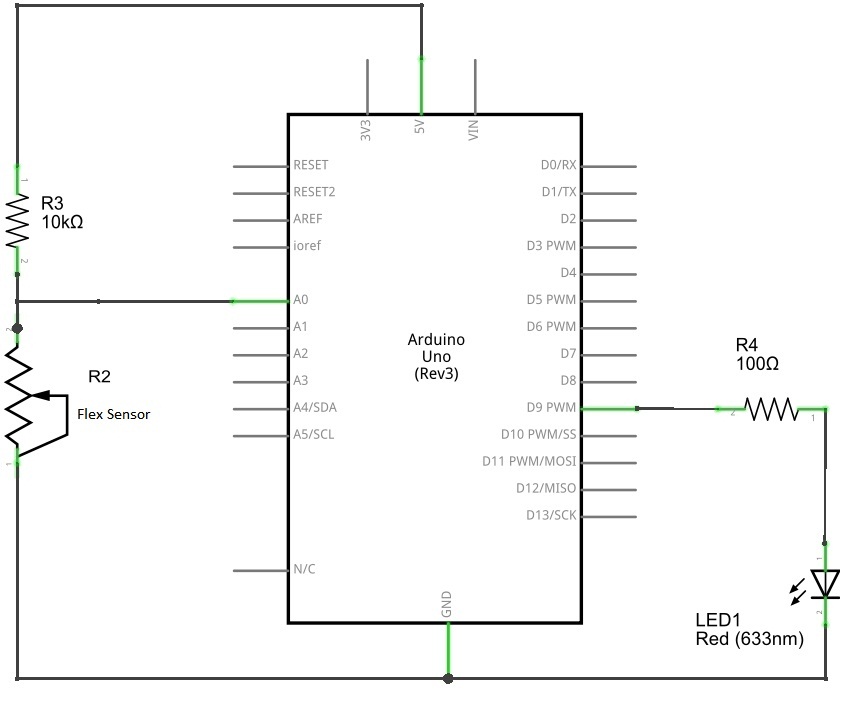
Here the LED connected with PWM output pin of arduino. When the resistance of flex sensor change the pwm output pulse will change hence the intensity of LED varies with respect to sensor value.
Arduino Flex Sensor sketch code
[code]
/*www.theorycircuit.com*/
const int flexpin = 0;
int led = 13;
void setup()
{
Serial.begin(9600);
}
void loop()
{
int flexposition; // Input value from the analog pin.
flexposition = analogRead(flexpin); // Read the position of the flex sensor (0 to 1023):
analogWrite(led, flexposition);
Serial.print(“sensor: “);
Serial.print(flexposition);
delay(20);
}
[/code]
Components List
| S.No | Name | Quantity |
| 1. | Arduino uno | 1 |
| 2. | Flex sensor | 1 |
| 3. | LED | 1 |
| 4. | Resistors | 10K Ω 100 Ω |
| 5. | Connecting wires | as required |