
Last Updated on March 28, 2024
The voice Recognition module V2 gives perfect way for voice controlled Automation, this module can be easily interfaced with Arduino board and other Microcontrollers which supports TTL or UART that is Tx & Rx. This module has a IC called “SPCE061A” it is a 16-bit sound controller with 32K X 16 flash memeory. This sound controller IC is the heart of this module.
SPCE 061A Block Diagram
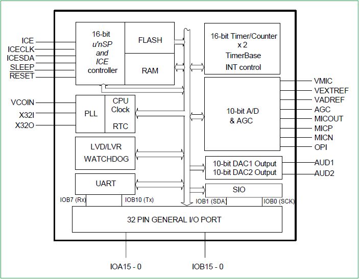
It is a 16-bit Architecture Microprocessor developed by SUNPLUS technology. It is capable of handling complex digital signal in sound process and voice Recognition. It contains 32-K word flash memory plus a 2K-word working SRAM, 32 programmable multifunctional I/Os, two 16-bit timers/counters, 32.7KHz Real Time Clock, eight channels 10-bit ADC and 10 bit DAC output and Mic Amplifier with auto gain controller.
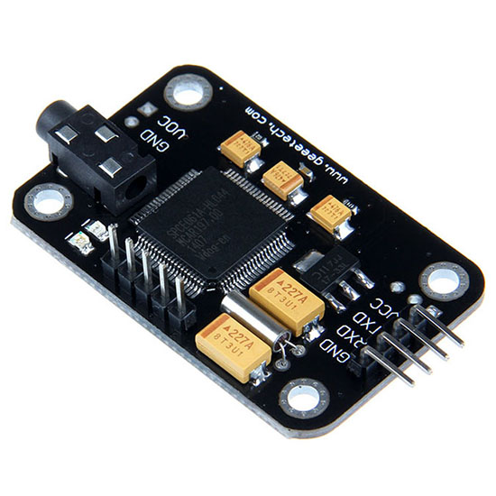
Voice Recognition Module V2
It can store 15 voice instructions in 3 groups with 5 voice instructions in one group. It has two power supply pins Vcc & Gnd and consumes 4.5 V to 5.5 Volt with less than 40mA current. The Tx & Rx pins makes UART communication possible to microcontrollers.
We cannot directly plug and play this module with Arduino or any other microcontrollers to get Voice Recognition ability follow these steps.
- Recording Voices
- Making Hardware connections
- Uploading Code
Recording Voices
Initially the module don’t know who you are? so we need to teach them and make our voice as familiar one.
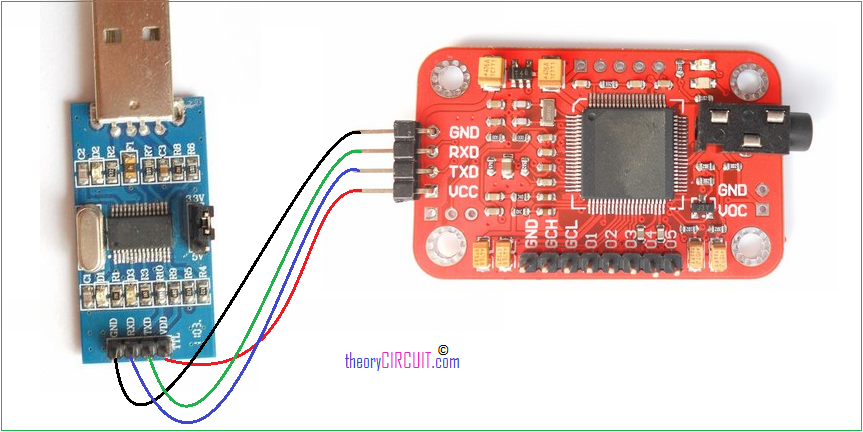
Connect the module with UART to USB converter and Interface with computer make sure the following connections.
USB-TTL module VR module
+5V Vcc
GND GND
TXD RXD
RXD TXD
Install or update USB-TTL module driver in your systems device manager. (for more reference).
After that we need Serial tool to communicate with the voice recognition module, Get Access Port Serial tool here.
Install and open Access port and set the following in settings, ie. baud rate: 9600, Parity bit: None, data bit : 8, stop bit : 1, send format: HEX, Receive format: Char.
Now start recording as follows.
Command format is “Head + Key”. “Head” is a 0xaa, and “Key” can be any of the commands that the VR module recognizes:
For Example Command-
0XAA11 (key=0X11) performs the following function-
Begin to record instructions of group 1
0XAA12 (key=0X12)
Begin to record instructions of group 2
0XAA13 (key=0X13)
Begin to record instructions of group 3
0XAA21 (key=0X21)
Import group 1 and ready for voice instructions.
0XAA22 (key=0X22)
Import group 2 and ready for voice instructions.
0XAA23 (key=0X23)
Import group 3 and ready for voice instructions.
0XAA33 (key=0x33)
Change the baud rate to 9600bps.
0XAA37 (key=0X37)
Switch to compact mode.
0XAA01 (key=0X01)
Delete the instructions of group 1.
0XAA02 (key=0X02)
Delete the instructions of group 2.
0XAA03 (key=0X03)
Delete the instructions of group 3.
0XAA04 (key=0X04)
Delete the instructions of all the three groups.
0XAA70 (key=0X70)
Reset serial port to 9600 baud rate, 8 data bits, no parity, 1 stop bit.
————————————————————————————————
Send: 0xaa11
Receive (in Common Mode):
START
No voice // I did not make any sound. So it replied such message
START
Speak now
Again
START
Speak again now
Different // I spoke another words for the second time. So it replied such message
START
Speak now
Again
START
Speak again now
Finish one // recording one instruction successfully
START
Again
START
Finish one
START
Again
START
Finish one
START
Again
START
Finish one
START
Again
START
Finish one
Group1 finished! // recording group 1 successfully
Now group 1 training is done and similarly you can train other groups.
Please record the following voice instrctions in order :
1.WHITE
2.RED
3.GREEN
4.BLUE
5.OFF
Then send command 0xAA21 to import group 1. Remove the voice recognition module after successful recording with command hex code.
Making Hardware Connection
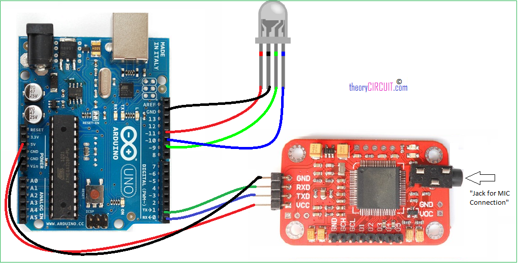
Make the connections as per the hookup diagram connect the Mic in provided jack and upload the following arduino sketch disconnect TXD and RXD pin while uploading the Arduino Code.
Arduino Code
int redPin = 11; // R petal on RGB LED module connected to digital pin 11
int greenPin = 9; // G petal on RGB LED module connected to digital pin 9
int bluePin = 10; // B petal on RGB LED module connected to digital pin 10
byte com = 0; //reply from voice recognition

void setup()
{
Serial.begin(9600);
pinMode(ledPin, OUTPUT); // sets the ledPin to be an output
pinMode(redPin, OUTPUT); // sets the redPin to be an output
pinMode(greenPin, OUTPUT); // sets the greenPin to be an output
pinMode(bluePin, OUTPUT); // sets the bluePin to be an output
delay(2000);
Serial.write(0xAA);
Serial.write(0x37);
delay(1000);
Serial.write(0xAA);
Serial.write(0x21);
}

void loop() // run over and over again
{
while(Serial.available())
{
com = Serial.read();
switch(com)
{
case 0x11:
color(255,255,255); // turn RGB LED on -- white
break;
case 0x12:
color(255, 0, 0); // turn the RGB LED red
break;
case 0x13:
color(0,255, 0); // turn the RGB LED green
break;
case 0x14:
color(0, 0, 255); // turn the RGB LED blue
break;
case 0x15:
color(0,0,0); // turn the RGB LED off
break;
}
}
}

void color (unsigned char red, unsigned char green, unsigned char blue) // the color generating function
{
analogWrite(redPin, red*102/255);
analogWrite(bluePin, blue*173/255);
analogWrite(greenPin, green*173/255);
}
how can I import more than one group in VR v3? please help me.
This board support is limited.