
Last Updated on March 16, 2024
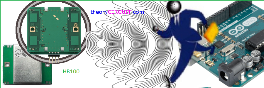
For Electronic Circuit designers, Makers and Hobbyists movement detection & Measurement of an object or person is simple task by using PIR sensor or Ultrasonic sensor but it is some what difficult to measure the movement speed. The HB100 Miniature Microwave motion sensor makes it easy to measure movement and speed.
HB Series of microwave motion sensor module are X-Band Mono-static DRO Doppler transceiver front-end module. These modules are designed for movement detection, like intruder alarms, occupancy modules and other innovative ideas. The module consists of Dielectric Resonator Oscillator (DRO), microwave mixer and patch antenna
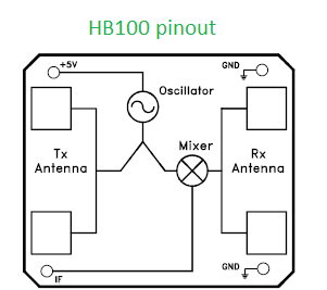
HB100 Sensor Pinout
Features
* Low current consumption
* CW or Pulse operation
* Flat profile
* Long detection range * X-Band Frequency 10.5 GHz * Operating Voltage 4.5V to 5.2V * DC level (0.01 to 0.2 Vdc) * Fd= 19.49V (Velocity in km/hour) or 31.36V (V in mile per hour) Fd=> Doppler frequency (If a target is moving straight toward or away from HB100 (Ft = 10.525 GHz))
Radiation Pattern
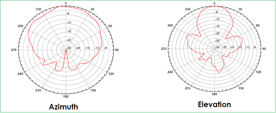
The radiation patterns of the antenna and their half power beam width (HPBW)
The module to be mounted with the antenna patches facing to the desired detection zone. The user may vary the orientation of the module to get the best coverage.
Doppler shift
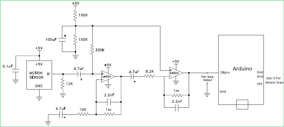
Doppler shift output from IF terminal when movement is detected. The magnitude of the Doppler Shift is proportional to reflection of transmitted energy and is in the range of microvolts (μV). A high gain low frequency amplifier is usually connected to the IF terminal in order to amplify the Doppler shift to a processable level. Frequency of Doppler shift is proportional to velocity of motion. Typical human walking generates Doppler shift below 100 Hz. (hb100_microwave_sensor_datasheet)
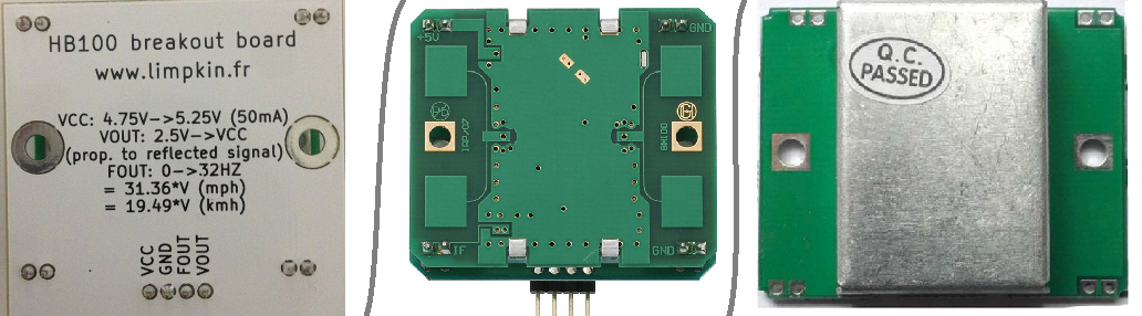
HB100 Sensor Breakout board
Note
- The radiated emissions of HB100 is designed to meet the requirements of Federal Communications Commission (FCC) rules, Part 15, Section 15.245 (use within a building or to open building door)
- The Received Signal Strength (RSS) is measured at the total 2 ways path loss of 93dB.
- The noise voltages are measured from 10 Hz to 100 Hz at the output port, inside an Anechoic chamber.
- CAUTION: ELECTROSTATIC SENSITIVE DEVICE. Observe precautions for handling and storage. (hb100_microwave_sensor)
Interfacing HB100 with Arduino
Arduino Code
#include “FreqPeriod.h”

double lfrq;
long int pp;

void setup() {
Serial.begin(9600);
  FreqPeriod::begin();
  Serial.println(“FreqPeriod Library Test”);
}

void loop() {
  pp = FreqPeriod::getPeriod();
  if (pp) {
    Serial.print (“period: “);
    Serial.print(pp);
    Serial.print(“ 1/16us / frequency: “);

  lfrq = 16000400.0 /pp;
  Serial.print(lfrq);
  Serial.print(“ Hz “);
  Serial.print(lfrq/31.36);
  Serial.println( “ Mph “);
}
}
For more about code and library : https://docs.google.com/document/d/1CVdH3UVTROaJ4_Bgsx_-hyg5_LvoNxYiB13pPRN9gzU/edit
Reference
- https://www.youtube.com/watch?v=PpU7R5LMUs4
![]() hb100_microwave_sensor_datasheet
hb100_microwave_sensor_datasheet
going further (Interesting)
where i can get the HB100 Sensor Breakout board ?
Hi ijon you can get here.
https://www.amazon.com/SMAKN-Microwave-10-525GHz-Doppler-Detector/dp/B00FFW4AZ4
There is only one guy making them. I have seen guys use a bread board and got it working.
Alternatively just design your own.
If you can’t the only place to buy from is here:
https://www.tindie.com/products/limpkin/hb100-doppler-speed-sensor-arduino-compatible/
Microwave boards are available cheaply, however the interface would have to be worked on.
http://www.ebay.co.uk/itm/291982694120?_trksid=p2057872.m2749.l2649&ssPageName=STRK%3AMEBIDX%3AIT
The “FreqPeriod Library Test” code requires the IF to be connected to the pin 7 of the Ard UNO not the pin 8, careful with that.
very much thankful for the pin suggestions. Is it possible to use lcd keypad shield where pin 8 and 7 are used by lcd. The pin in the IDE is (8, 9, 4, 5, 6, 7). kindly suggest.
Lifesaver man, Thanks a lot. Set everything up and could not figure out what was wrong until I saw your comment here.
hi! this post was really useful to me, but how can I regulate the distance?
because I want to detect objects within a range of 3 meters or less
In the amplifier schematic, is the small m in the 1m resistor for mili or mega and just not capitalized?
in resistor code M is Megaohms ..nothings else..
Sir, is there a way to code this library which will Raspberry pi?
which will work in*
Gooday – I am a newbie and have got the code to compile but I do not yet know how to set the pins. Where does the input signal go too on the Arduino. I have built the amplifier to support the HB100. I want to use this unit to track any movement around the house for security. Thank you in advance – Lee
Is there any Doppler radar sensor for arduino which can give analogue output ??
Hi, you can try other AgilSense modules here: http://www.agilsense.com.
Hello! When I tried to compile your code, Arduino highlighted a line in the code (see below) and stated “stray ‘\342’ in program”. What does this mean and how do I rectify this problem?
Here is the highlighted line of code:
Serial.printIn (“Mph”);
‘\342’ means there is a problem with unicode in codings ! if you just copy and paste the code you will encounter this kind of problems ! just change double quotations in print statement !
can i use it for measuring the smoothness or roughness of earth surface .
what do you suggest me for measuring the roughness of earth,
where do i get the library function for microwave doppler radar for arduino..plz can you helpout with it
for the arduino UNO , what are the spec ?
hi, i tried with PD-V11 to make it work but no luck 🙁 i use arduino mega what can it went wrong
Can anyone advise how to connect this to an arduino mega?
Hi,
Can Hb100 be used for stationery vehicle detection?
Hey Ramesh, no it can’t. Its only for moving targets.
Hey, I tried this circuit but it will give me constant output voltage 2.5V at second op-amp and constant 1.4V at the output of first opamp. so, I can not able to detect speed, what can I do?
Barely Check VOUT and FOUT pins of HB100 breakout board and then implement in op-amp circuit.
I tried this code, pre amp circuit and library (Freqperiod.h, not FreqMeasure.h as your link). But output of pre amp circuit is 0.3V, i think it must be about 2.5v. Screen just print “FreqPeriod Library Test”. When i touch microcontrller on arduino uno, TX led lights and screen print a lot of value. Help me, please!
Just Check the hookups of pre amp circuit and try again, hope you will get.
hey can it detect the heart beat of a human who is stable?
Hi sripaad
The answer is No, you can use heart beat sensor to detect heart beat of a stable human.
Hi, I’m a beginner. What is the meaning of this ‘Pre-Amp Output’? What can I do with it?
The circuit needs only 2 amplifiers, so you can use LM358 instead of LM324
translation ~ Hi, I’m a beginner. I want to connect it to an ESP32—is that possible? So, going from the HB100 to the LM358 and then to the ESP32’s GPIO34 pin—do I use the same code? Please help…
Hi, I’m a beginner. I want to connect it to the ESP32. Is it possible? So, from the HB100 to the LM358 and then to the GPIO34 pin of the ESP32, is it using the same code? Please help me..