Last Updated on March 16, 2024
Seven Segment display widely used to project numbers in many applications and here is the simple driver circuit to convert BCD to 7 Segment display designed by using CD4511. It can drive common cathode seven segment display.
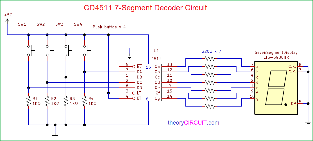
Here for an example push button switches are taken as input and single digit seven segment display is being driven by IC CD4511 according to the BCD input from Push buttons.
Circuit Diagram
Components Required
- Common Cathode 7-Segment display
- IC CD4511
- Push button Switch = 4
- Resistor 1KΩ = 4
- Resistor 220Ω = 7
- Battery
Construction & Working
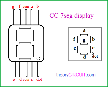
Connect Four push button switches between bias through Resistor and it will be act as BCD logic input to the seven segment driver IC. Connect A, B, C, D (DA to DD) to corresponding BCD logic input push button as shown in the circuit diagram. Connect Seven segment display output from CD4511 to CC 7-segment display Qa – a to Qg – g and connect DP to ground because this circuit has only one digit. Finally connect Common cathode (CK) pin to Gnd and apply bias to Circuit.
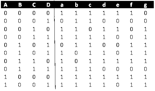
CC 7-Segment Truth table
According to the truth table logic 1 represents segment LED glowing and Logic 0 represents segment LED OFF condition. Hence for the BCD four digit input Seven segment LED shows corresponding Numbers.


