
Last Updated on June 27, 2024
Interesting way to learn about electronics is building it ourselves, here is the simple and useful hobby project called Clap Switch Circuit. It contains only two BC547 Transistor and condenser mic then few easily available components.
By making this circuit, we can use it to play or to control home appliances. In order to make it ON and stay or OFF and stay with one clap, we need to add Flip Flop. The following circuit makes LED glow for few seconds for one clap and then automatically turns off. To increase the ON time we can change the R1, C1 values.
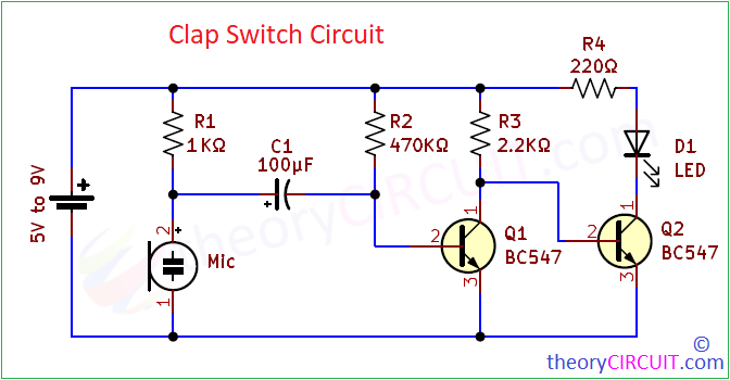
Clap Switch Circuit Diagram
Components Required
- Condenser Mic = 1
- Resistor 1KΩ, 470KΩ, 2.2KΩ, 220Ω = each one
- Capacitor 100 µF = 1
- Transistor BC547 (NPN) = 2
- 5mm LED = 1
- DC Supply 5V to 9V
Working Video
Construction & Working
When we produce high pitch sound or clap, the condenser microphone receives and converts sound wave into electric signal. Here we are going to use this Condenser mic as switch. Here Transistor Q1 receives enough voltage (greater than 0.7V) to the base terminal through R2 Resistor and collector voltage through R3 Resistor, hence the Q1 transistor stays in ON condition when we apply supply to this circuit.
So that Transistor Q2 don’t receive enough bias because all supply through R3 grounded by Q1 transistor. So the Q2 stays in OFF condition and LED connected in collector terminal also in OFF condition. When the clap or high pitch sound occurs, the condenser mic makes short duration conduction to Ground supply, so the C1 capacitor charge gets discharge through condenser mic to GND, the charge difference in C1 attracts all the bias from R2 Resistor to C1. So the transistor Q1 don’t get base supply and so it becomes turn OFF and no conduction to Ground.
Here the supply from R3 makes transistor Q2 turn ON and so the LED connected in series with collector terminal becomes “ON” for short duration. Slowly C1 gets charge and once fully charged then the supply from R2 reach Q1 base and makes it ON so the Q2 becomes OFF hence the LED comes to “OFF” condition until another sound spike occurs.