
Last Updated on March 16, 2024
When we forgot to turn off the home appliance then the electricity bill will turn on us, so it is important to turn off any Electrical appliance when not in use in order to save energy and money. Here a simple AC power outlet with Timer circuit designed to Automatically turn ON/OFF home appliance at particular time with the help of IC555 timer and AC power socket.
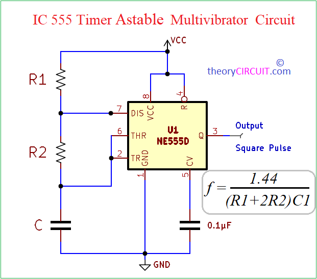
Here the Timer IC 555 configured in Astable Multivibrator mode, To turn ON and turn OFF appliance connected to the AC power outlet periodically. As we know the Astable Multivibrator circuit using the 555 timer IC operates as a continuous square wave generator. In this configuration, the Threshold and Trigger pins are connected together, forming the Control Voltage input. The external components, namely resistors (R1 and R2) and a capacitor (C1), determine the timing characteristics of the circuit. Initially, with the capacitor discharged, the voltage at the Control Voltage input is low.
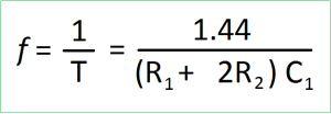
As the capacitor charges through R1 and R2, the output of the 555 timer goes high when the voltage across the capacitor reaches 1/3 of VCC. Subsequently, when the capacitor discharges through R2 and reaches 2/3 of the VCC, the output goes low. This cyclical process repeats, generating a continuous square wave at the output. The frequency of the square wave is determined by the values of R1, R2, and C1. Use Astable Multivibrator Calculator for frequency and time period calculation.
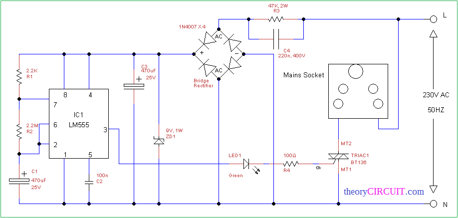
AC power outlet with Timer Circuit Diagram
This circuit involves in operating High Voltage that can give lethal shock, Handle with Extreme caution
Components Required
- Timer IC NE555
- Bridge Rectifier Module or Diode 1N4007 X 4
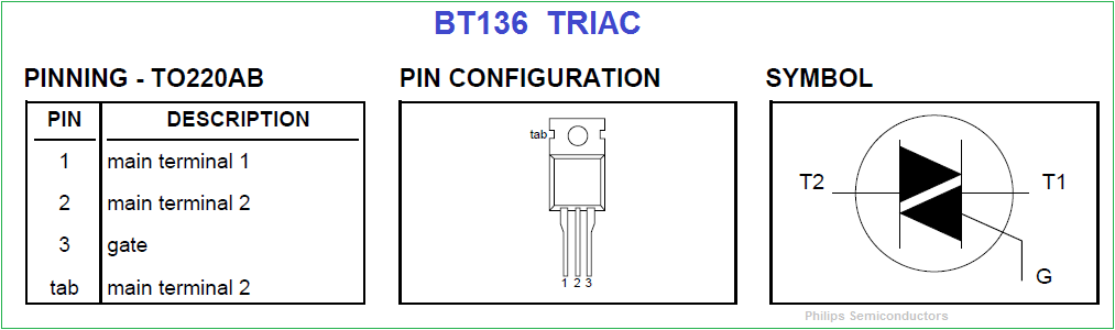
- TRIAC BT136
- Zener Diode 9v
- LED Green
- Electrolytic Capacitor 470uf = 2
- Ceramic Capacitor 100nF
- Resistor 2.2KΩ, 2.2MΩ, 47KΩ, 100Ω each one (all are 1 Watt)
Construction and Working
This circuit is designed to work without step down transformer, it uses the mains AC supply provided for AC plug point. The X rated capacitor C4 and resistor R3 decreases the AC supply through capacitive reactance and parallel Resistor R3 discharges the supply across capacitor when there is no power supply. The bridge Rectifier converts AC supply into DC and zener diode ZD1 Regulates the DC supply as constant near to 9 volts, C3 capacitor filters DC supply before it reaches the timer circuit.
The Timer circuit using IC555 designed as Astable multivibrator to produce long duration timing pulse, we can vary the time delay by using R2 and C1 values.
The BT136 TRIAC is connected between the AC socket and neutral supply line, Gate terminal is connected with output pin of timer IC. When the high pulse rise it turn ON the TRIAC and makes power supply available at mains socket for particular time period.
TRIAC turned off when the low pulse came from the timer IC, then there is no power supply available at mains socket by the way we can make any electrical appliance to turn ON and OFF periodically. Above circuit with same Timing components to the 555 timer gives approximately 23 Minutes ON time and 23 Minutes OFF time. You can modify the timer circuit into monostable for to do automatic OFF only.
BT136 series TRIACs
Instead R2 2,2M potentiometar 2,2M for regulation time
yes you can use Potentiometer for to change Regulation Time.