
Last Updated on March 16, 2024
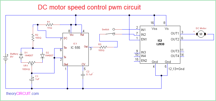
The DC Motor used in many applications, and some applications requires speed control of DC motor some times it requires rotation direction control. Here the simple DC motor speed control PWM circuit is constructed by using IC 555 and motor driver IC L293D.
In following schematic IC 555 timer acts as a PWM generator and H Bridge motor driver IC L293D takes responsibility to drive motor depends on the PWM input signal. Here motor rotation direction can be changed by changing input pins.
PWM Signal
When we apply DC supply to the motor it starts to rotate the shaft but we cannot control its RPM (Revolutions per minute), when we apply PWM signal as a supply to DC motor depends on PWM duty cycle we can control DC motors RPM.
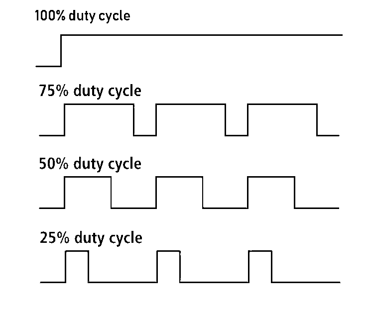
Here duty cycle is percentage of ON time in one period and depends on the ON time duration and pulse count motor speed (RPM) get varies.
H-Bridge Operation
H-Bridge or motor driver ICs like L293D are used to convert low power control signal to power enough signal to drive motors and for change the supply direction of load motor.
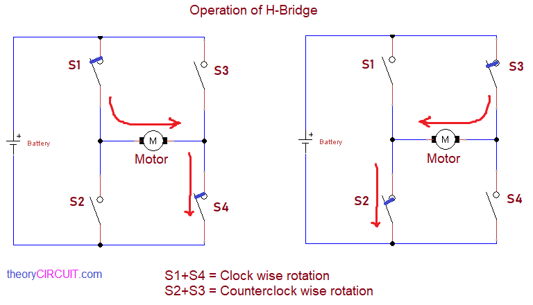
depends on the switch open and close the motor gets forward and reverse direction supply hence the rotation varies clock wise or counter clock wise depends on the switch positions, this is how the H-Bridge motor drivers are works.
Circuit Diagram
Components Required
- DC Motor (1000 RPM) 9V
- IC L293D
- IC 555
- 9 V battery
- Variable Resistor 100KΩ
- Resistor 1KΩ
- Resistor 100Ω = 2.
- Capacitor 1μF electrolyte, 0.1μF
- Diode 1N4007=2
- toggle switch
- Bread board
- Connecting wires
Construction & Working
Here timer IC 555 employed as a square pulse generator depends on the variable resistor value the output pulse width or duty cycle gets change and the output from IC 555 directly apply to the motor driver H-Bridge IC L293D through toggle switch. By using toggle switch we can change the input pin of L293D. The DC motor is connected between out 1 and out 2.
L293D motor Driver
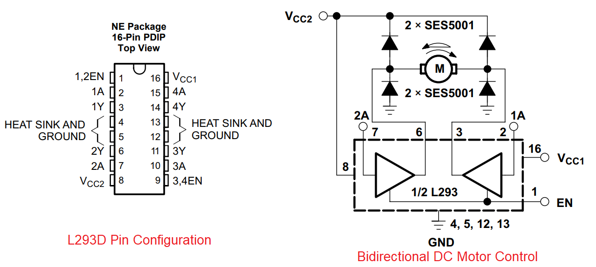
The IC L293D has 16 pin and it can drive two motors same time. Here the schematic shows bidirectional DC motor control.
Ill try it and observe
looks nice,
it would be more nice if someone can make it wireless