Last Updated on October 8, 2025
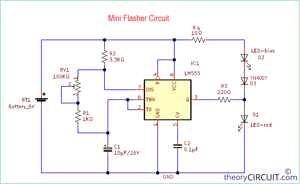
Multipurpose Mini Flasher is designed by using timer IC LM555 and two LEDs, these two LEDs are glows alternatively according to the timer IC output. By variable Resistor used in this circuit we can adjust the blinking speed of LEDs.
This Mini Flasher circuit works like astable multivibrator and gives continuous square pulse output. This circuit can operate by using 6 volt to 10 volt power source, here we used battery in schematic (you can use any power source which provides less than 400 mA).
Circuit Diagram
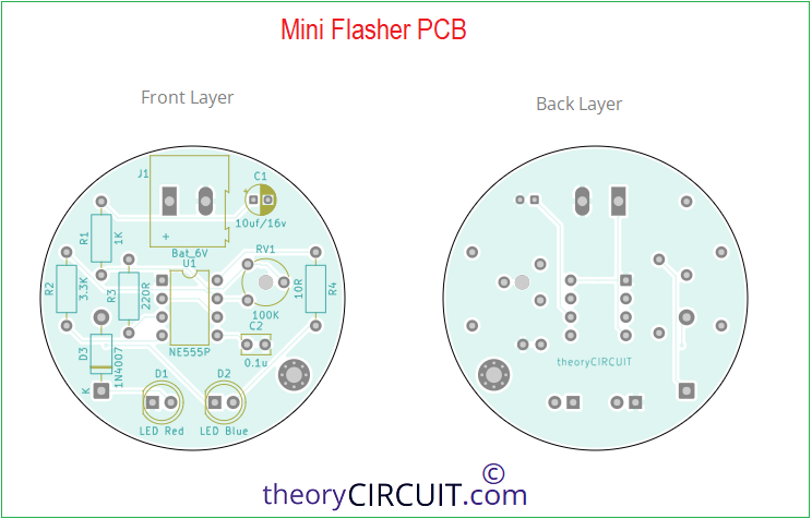
Components Required (BOM)
| 1 | C1 | 10uf/16v | CP_Radial_D4.0mm_P2.00mm | 1 | ||
| 2 | C2 | 0.1u | C_Disc_D3.8mm_W2.6mm_P2.50mm | 1 | ||
| 3 | R1 | 1K | R_Axial_DIN0207_L6.3mm_D2.5mm_P10.16mm_Horizontal | 1 | ||
| 4 | R2 | 3.3K | R_Axial_DIN0207_L6.3mm_D2.5mm_P10.16mm_Horizontal | 1 | ||
| 5 | R3 | 220R | R_Axial_DIN0207_L6.3mm_D2.5mm_P10.16mm_Horizontal | 1 | ||
| 6 | R4 | 10R | R_Axial_DIN0207_L6.3mm_D2.5mm_P10.16mm_Horizontal | 1 | ||
| 7 | D1 | LED Red | LED_D5.0mm | 1 | ||
| 8 | D2 | LED Blue | LED_D5.0mm | 1 | ||
| 9 | D3 | 1N4007 | D_DO-41_SOD81_P10.16mm_Horizontal | 1 | ||
| 10 | U1 | NE555P | DIP-8_W7.62mm | 1 | ||
| 11 | RV1 | 100K | Potentiometer_Piher_PT-6-V_Vertical_Hole | 1 | ||
| 12 | J1 | Bat_6V | TerminalBlock_Altech_AK300-2_P5.00mm | 1 |
Construction & Working
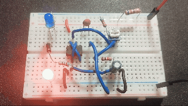
For an experiment here we constructed this circuit on a PCB and all components involved in this prototype are THT elements. After Printed Circuit Board Assembly, apply power supply to the board and then timer IC LM555 starts to oscillate Square pulse, duty cycle of the pulse is depends on the value of RV1 and C1. By varying RV1 we can get different range of duty cycle.
At the output terminal two LEDs are connected through R3 Resistor and these two connected in antiparallel way. Hence for both positive and negative cycle output LEDs will glow alternatively.
Timer IC 555 Astable Multivibrator Calculation

Here, RA = R2 Resistor, RB = RV1+R1 Resistors, C = C1 Capacitor value.
PCB
Mini Flasher Circuit using IC LM555 Gerber Files.
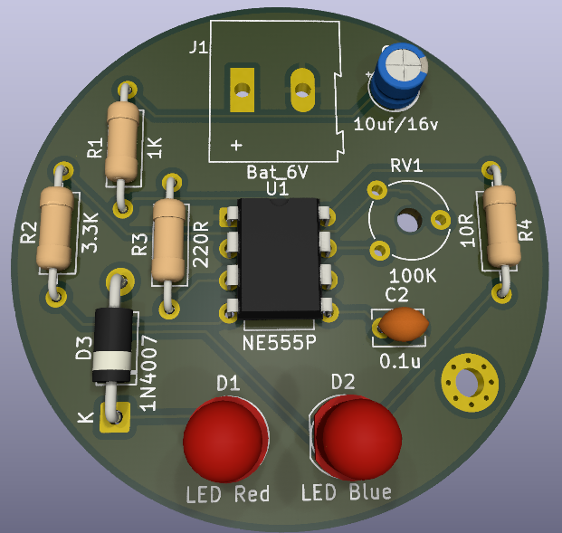
Interactive Board Viewer


Prototype on Breadboard
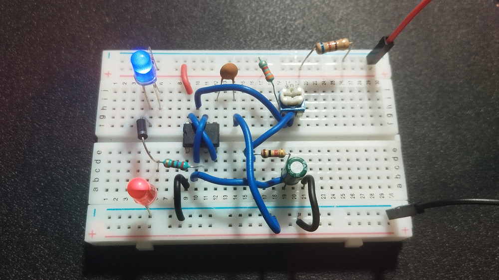
Working!