
Last Updated on December 14, 2025
It is important to understand few things before start to code ESP 01 or ESP 01s WiFi Module, First thing ESP8266 is a WiFi SoC (System on Chip) developed by Espressif systems, This Integrated chip contains 32 bit microcontroller, so it can run program and communicate via WiFi. This is the key reason it become so popular in IoT projects. ESP8266 IC have 2.4GHz Wi-Fi (802.11 b/g/n) block, TCP / IP stack and communication protocols like GPIO, PWM, SPI, I2C, UART and also have internal ADC block. All this in a very small package, so that is is very easy to deploy it as a IoT node without extra microcontroller.
ESP 01 Module
ESP 01 and ESP 01s are similar development boards with small memory size changes. Here ESP 01 / ESP 01s module will have same ESP8266 chip, external memory chip and on board wifi antenna. One small drawback is, it may not have USB to TTL serial converter so that you need external device to code it.
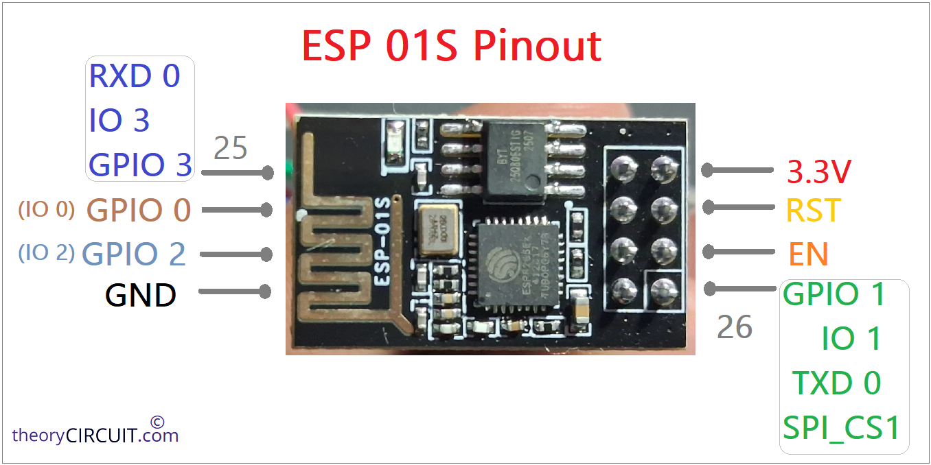
ESP 01s Module Pinout
How to Code ESP 01 module?
Use external USB to TTL serial converter if you have one or you can use any microcontroller board which have on board USB to Serial converter. (It is important to keep that microcontroller in Reset mode to use USB to Serial converter for ESP 01 module).
Here we use Arduino nano Microcontroller board which have CH340C USB to Serial TTL converter.
ESP 01 Program Mode
To write code into ESP8266 microcontroller in ESP 01 / 01s module we need to put it in Program mode by making the following wiring.
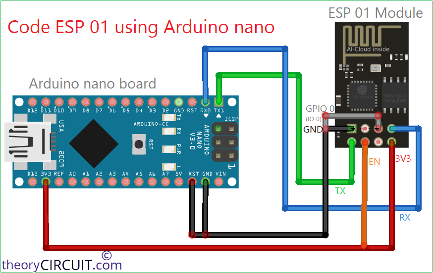

| ESP 01 / ESP 01s Module | Arduino nano Board |
| Tx | TX1 |
| Rx | RX0 |
| EN | 3.3V |
| 3V3 | 3.3V |
| GND | GND |
| IO 0 (GPIO 0) | GND |
Keep Arduino nano RST pin to GND to make CH340C Chip dedicated for ESP 01, (keep in Reset mode, any development board you use to upload code to ESP 01 module, so the on board USB to Serial converter dedicated to ESP 01 module).
Now the USB to TTL serial Converter on Arduino nano board is connected with ESP 01 module.
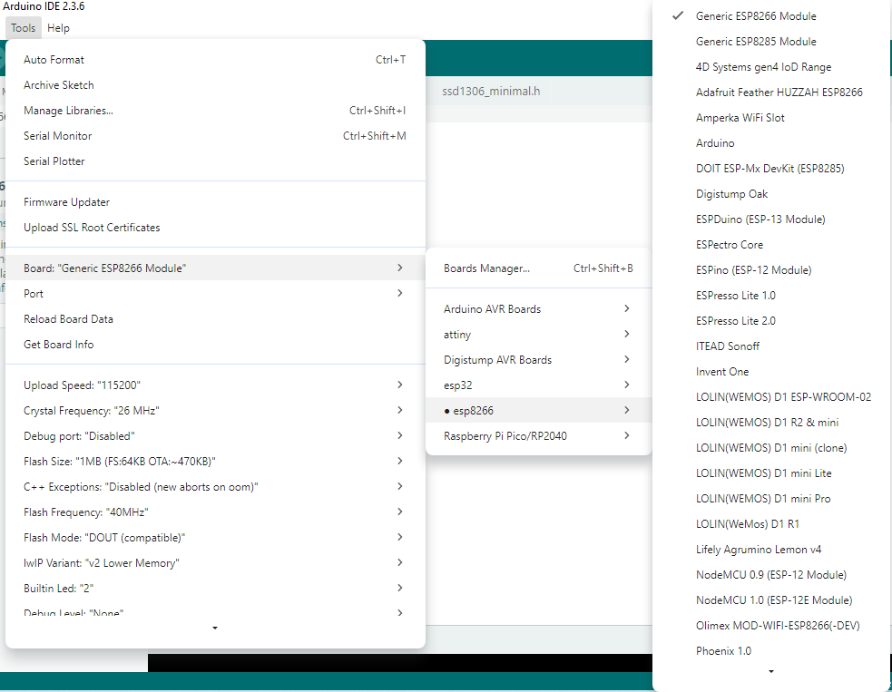
Writing code to ESP 01 using Arduino IDE
The ESP 01 and ESP 01s module which have ESP8266 microcontroller supports Arduino code and so we can use Arduino IDE to write code to it. First thing you need to download ESP8266 board setup through Arduino boards manager by pasting the url: http://arduino.esp8266.com/stable/package_esp8266com_index.json

Then go to boards manager and Install ESP8266 board.

Now connect Arduino nano board (any of your development board) with computer and note the port number, here we got COM6 (you may get different number) and choose the board as Generic ESP8266 module and write code then upload.
#define LED 2

void setup() {
  pinMode(LED, OUTPUT);
}

void loop() {
  digitalWrite(LED, LOW);   // ON (active LOW)
  delay(1000);
  digitalWrite(LED, HIGH);  // OFF
  delay(1000);
}
If you see any error just disconnect and connect the USB with computer and try again.
After uploading code you may not see any output from ESP 01 or ESP 01s module, because it is in program mode.
ESP 01 Run Mode
To make the code run you need to put ESP 01 module to run mode for that just remove all the wires and keep only biasing wirew.
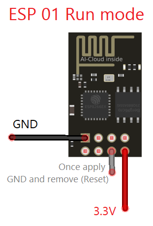
Then make ESP 01 Reset pin to GND (Ground) once and then remove from ground (you may use push button). Now you can see the code running. By this way we can run any code after uploading.