
Last Updated on April 4, 2024
Power supply is essential for every electronic circuits to operate, most of the active device made with silicon semiconductor or germanium semiconductor requires proper forward bias and voltage, fluctuations in power supply may interrupt operations of those device. Microcontrollers and some sensors are bias (Input Voltage and Current) sensitive elements. So it is very important to test and build electronic circuits. Here is the simple and traditional way of getting Regulated DC power supply by using Positive Voltage Regulators IC 7812 and IC 7805. Following Single Input 12V and 5V DC Power Supply Circuit is suitable for biasing most electronic components and circuits which consuming 1.5 Amps current.
This circuit designed with Input supply indicator and 12V, 5V output supply indicator LEDs. So that we can ensure the presence of power in each stage. To build this circuit we need a Stepdown transformer., it can be either 12-0-12Vac, 0-16Vac or 24Vac Output stepdown transformer and maximum 1.5A current rating.
Transformers are takes High Voltage AC (180Vac to 240Vac) input, handle with extreme care.
Read here to know more about stepdown transformer and its operation.
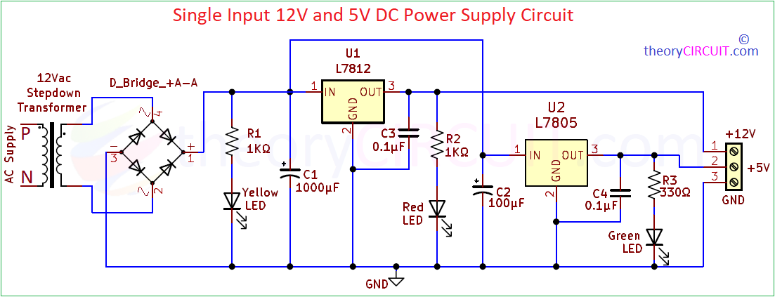
Circuit Diagram
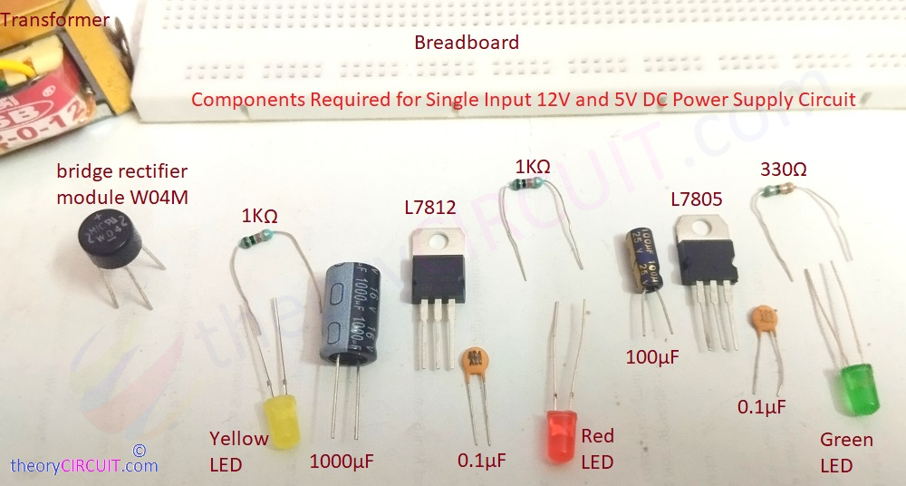
Components Required
- 12Vac (16Vac or 24Vac can also used) Stepdown transformer
- Bridge Rectifier Module W04M or Four 1N4007 in bridge form
- Positive Voltage Regulator IC 7812 and IC 7805
- Resistor 1KΩ = 2, 330Ω = 1
- Electrolytic Capacitor 1000μF/25V, 100μF/25V each one
- Capacitor 0.1μF (104) = 2
- LED yellow, Red, Green each one
- Connecting Wires
- Breadboard
Video
Construction & Working
Before start with construction few points about the positive Voltage Regulator,
IC 7812 and IC 7805
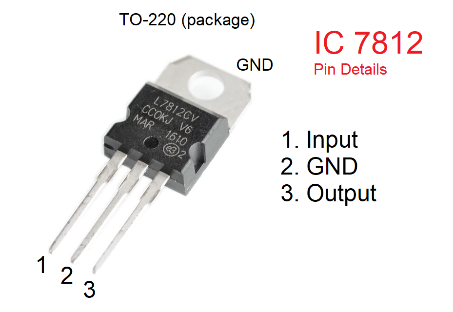
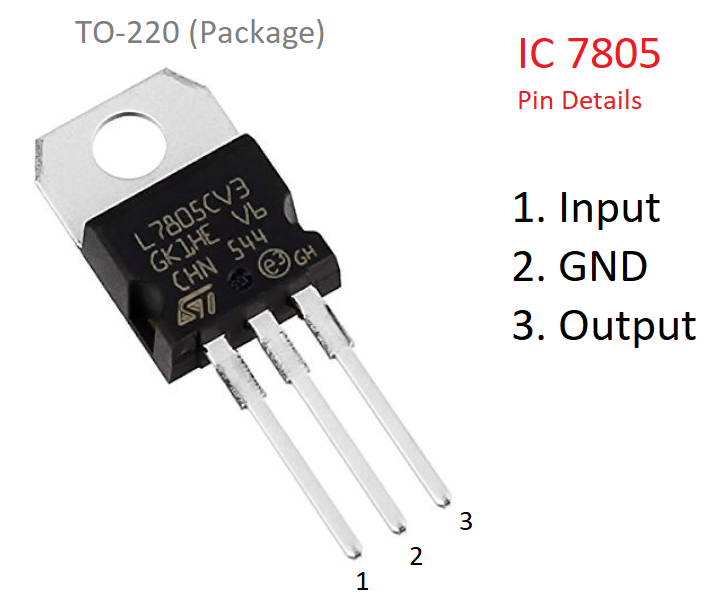
Voltage Regulator IC with 78 starting number indicates Positive Voltage Regulation. These three terminal Positive voltage regulators available in TO-220, TO-220FP, D²PAK and DPAK packages and several fixed output voltages like 5; 6; 8; 8.5; 9; 12; 15; 18; 24 V it is represented in last two digit of IC. Here we using 7812 (12 Volt Regulator) and 7805 (5 Volt Regulator). It can provide local regulation on PCB or breadboard, so that it avoids the distribution problems associated with single point regulation. These device have internal current limiting and thermal shutdown protection. It is recommended to provide heat sink for continuous 1 A current output operation.
Construction of this power supply circuit starts with selecting stepdown transformer and Bridge Rectifier, you can use W04M module or four 1N4007 Diode in bridge format to rectify AC supply into DC supply. This infilter and unregulated DC is indicated through Yellow color LED, Electrolytic Capacitor C1 filters DC supply and gives input to 7812 and 7805, now the internal blocks of these two positive voltage regulator makes regulation and gives Regulated 12V DC and 5V DC respectively.
Even though it is regulated there may be high AC spike occurs due to external interference to the main AC supply. To filter that kind of noise we used 0.1μF Capacitor at each output pins. Red LED indicates the presence of 12 Volt supply and Green LED Represents 5V DC Output. If you are unsure about choosing Series Resistor for LED then use this Calculator.
Test your components in breadboard before making soldering in PCB or Dot PCB board and use proper insulation for input main lines to the transformer.