
Last Updated on April 6, 2024
Rechargeable Batteries like Lead-Acid Batteries, Sealed Lead-Acid (SLA) Batteries and Nickel-Cadmium (NiCd) Batteries requires frequent charging depends on the usage. SLA batteries are known for its self discharge characteristics, so we need to do float charge or maintenance charge to keep the batteries in full charge condition. The following 12V Battery Charger Circuit with 555 Timer can be used as float charger or General purpose 12V / 1A battery charger with cut off time.
Charging battery is crucial aspect of their maintenance and proper operation. Applying Correct voltage and current to battery avoids overcharging. Make sure about the specifications of your battery meets with circuit output voltage and current before employing it to charge the battery.
Simple 12V battery charger circuit can be used, if you are manually charging battery or making top up. This battery charger with timer IC gives you minimum charging time 11 Minutes to maximum charging time 35 Minutes, it can be achieved by varying the Trimpot (RV1). Afte charging time over, it disconnects battery from power supply through SPDT Relay. Then again cycle starts, we can make it one time charge by configuring timer IC 555 in monostable mode.
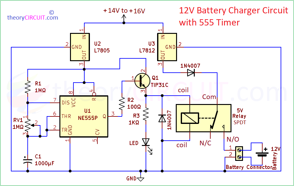
Circuit Diagram
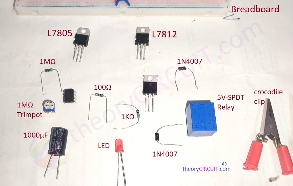
Components Required
- Positive Voltage Regulators L7805 and L7812 each one
- Timer IC 555
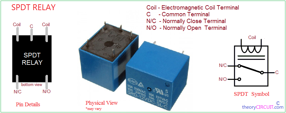
- 5V SPDT Relay
- Transistor TIP31C (NPN)
- Diode 1N4007 = 2
- LED
- Resistor 1MΩ, 100Ω, 1KΩ each one
- Trimpot 1MΩ
- Electrolytic Capacitor 1000μF
- DC Supply (14V to 16V / 1A)
- Crocodile clips
- Breadboard
- Connecting Wires
Working Video
Construction & Working
DC power supply with 5V and 12V output is required for this circuit, so that we used two positive voltage regulator Called 7805 and 7812. If you want start with power supply circuit then read here… Timer IC 555 Configured in Astable multivibrator mode to generate timing pulse based on timing components R1, RV1 (R2) and C1. This circuit gives ON and OFF time pulse between 11 minutes to 35 Minutes. You can change these components for your requirement, use Astable Multivibrator Calculator to calculate the time duration.
Output from 555 is connected with Base terminal of TIP31C (NPN) transistor and 5V SPDT Relay is connected at the Emitter terminal. Collector is biased with +5V DC. Transistor gets turn ON when the base terminal receives above 0.7V and makes conduction between Collector to emitter. In that time Relay coil gets supply and magnetize, so that it attracts Armature and makes contact between common terminal to N/O (normally open) terminal. Now the Battery receives DC Supply through L7812 output and GND. To indicate the charging an LED is also connected in the Emitter terminal of TIP31C. For reverse voltage protection from relay coil we used 1N4007 PN Junction diode in reverse across the relay coil. Another 1N4007 diode in the path of L7812 Output to avoid voltage reverse spike from the contacts of relay.
After the HIGH pulse (ON time), LOW (OFF time) pulse appears in the output, then the Transistor Q1 don’t receive enough voltage and goes to Off state. So there is no bias flow between Collector Emitter and the Relay imediately demagnetized and release Armature and makes common contact terminal to N/C (normally close) position. Now the battery don’t receive any voltage and disconnected from charging.
TIP31C Pinout
Points to Note:-
- This charger circuit gives 12V / 1A output, with time limit set by 555 Timer.
- It can be used to charge or float charge battery.
- Avoid connecting battery with more than 1A current rating with this charger circuit.
- Suitable for SLA, NiCd and Lead-Acid Batteries.
- Use +14V to 16V / 1 Amps power supply to this circuit.
- Use dot PCB board to solder this circuit and then employ it field.
- Check the output Voltage and Current using Multimeter or DMM display before connecting batteries.