Last Updated on March 16, 2024
Many times we forgot to turn off some home appliances when it not needed, due to this much power loosed without any use. To avoid this situation power saver circuit using PIR sensor can be used, this circuit turn off load device when a person exit from the room.
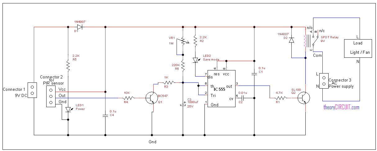
Circuit diagram
Construction and Working
Main part of this circuit is timer IC555 and PIR (passive infra red) sensor. This circuit receives trigger input from the PIR sensor and activates relay through timer IC output. PIR sensor output is directly fed into transistor BC547 base and then collector terminal is connected with threshold and trigger pin of IC555 through timing resistor and capacitor.
Here we can vary the sensitivity level and output pulse duration through timing resistor VR1. The LED2 connected with discharge pin shows the save mode of this circuit, the SL100 switching transistor drives output to the relay here you can use any switching npn transistor, before that refer the switching voltage level. In this circuit 9volt relay is used to control the load.
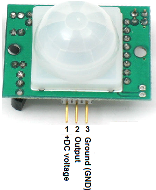
Pin details of PIR sensor
You can get datasheet of timer IC LM555 here.
For a simple beep upon motion, try connecting the PIR output (with 1K resistor) to pin 4 of a 555 oscillator with 1KHz tone. As the PIR settles in the first minutes, you hear a few beeps.