
Last Updated on March 16, 2024
Inverters are the device which converts DC (direct current) to AC (alternating current), and gives High woltage and current from low power battery source.
Inverters are very helpful to operate electrical appliances during power cut or shortage, Inverters can be classified based on the output terms like, Square wave, Modified sine wave and Pure Sine wave output Inverter.
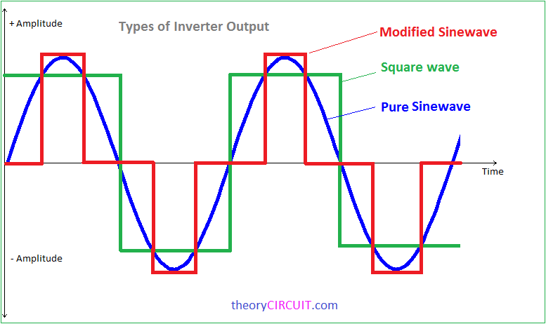
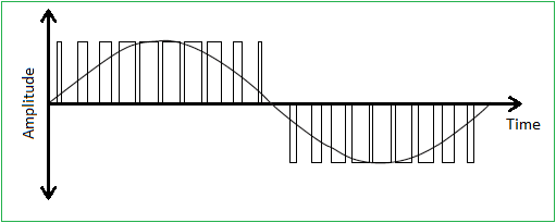
The square wave inverter are very simple and easy to make but that is not suitable for sensitive Electric appliances, Modified sine wave inverters are gives output as close as to the sine wave but not pure as much we have receive from wall outlet. PWM (Pulse Width Modulation) signal based inverters are produce output as pure sine wave and it can be used for any electric appliance that meets the inverter output range.
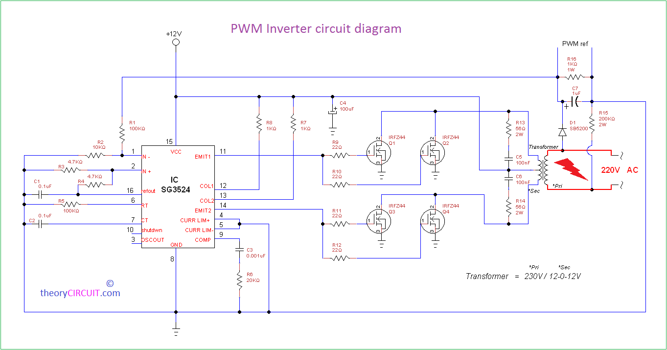
Simple and powerful PWM inverter circuit diagram designed with IC SG3524 (Regulating Pulse Width Modulator) gives upto 230V AC from 12V DC supply.
PWM Inverter Circuit diagram
Construction and Working
This Inverter circuit contains three stages,
- PWM Switching Pulse Generator
- Switching Device
- Step up Output Driver
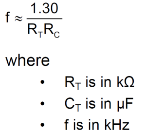
The PWM switching pulse generator is the main part of this circuit, which is responsible to produce PWM pulse according to the sine wave reference . The IC SG3524 gives fixed frequency PWM that can be varied by RT and CT element values.
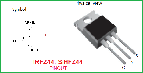
Output from Emit1 and Emit2 pins are directly fed into Switching device that is constructed by N channel MOSFET IRFZ44, the Q 1 and Q2 are drive by Emit1 output. Q3 and Q4 MOSFET are drive by Emit2 output from SG3524.
The step up Output driver contains a transformer 230V primary to 12-0-12V secondary with 2 Amp current rating and this transformer connected in Reverse to step up the voltage output. Sample output is taken by the small circuit to give the reference feedback to PWM regulator SG3524.
NOTE:-
[stextbox id=”warning”]High Voltage and Current output Circuit. Handle with Care and Safety measures[/stextbox]
- Change the RT and CT value to get required output.
- Use Heat sink over the MOSFETs
SINE PURE XA2206 ?
All the sg/ca 3524 circuits presented on the net are missing a vital component/circuit. That is to say the sg3524 has been wire to produce a fixed pulse width which does not produce a SINE WAVE behavior at the transformer. What is required is a means of modulating the pulse width by applying a 50/60 hz signal at pin 2 of the sg3525. This will vary the puse width and produce a SINE WAVE effect at the transformer.
Boa noite amigos, estou montando este inversor porem não consigo abaixar a frequência para 60Hz. pelo que vi no datasheet do sg3524 que a frequência minima e de 120Hz. preciso que o meu funcione com 60Hz. outra coisa a tensão de saída esta muito alta.
alguém poderia me ajudar. sera que se eu fizer um oscilador com um 555 de 60Hz e colocar a saída dele no pino 2 do sg3524, será que funciona? grato!
What is the frequency of this inverter circuit
Hello dear, I have a little problem with my sg3524 inverter. The voltage at pin 11 and 14 is half the input voltage, that’s 6.4v. Pls. help me.
What is the frequency of this inverter circuit
Not being an expert on the use of the sg3524 I would do the following. Disconnect the JFET gates fron the circuit and measure the pull-up voltage at pins 11/14. If the voltage is at or near 8 volts then the ca3525 is functioning properly which means (to me) the pull-up resistors are to low in value. They should be in the neighborhood of 120 ~ 220 ohms. If that does not correct the problem when you reconnect the JFETS then adding a small capacitor across the resistors along with a switching diode in parallel with the resistor/capacitor combination to allow the capacitor to discharge on the pull-down of the pulse. Capacitor should be more or less 50 pf.
P.S. – be sure the anode of the diodes are facing pins 11/14 so as to not allow the capacitor to feed a negative pulse to the gates.
Correction: MOSFETS NOT JFETS.
Hello I have a little problem with my sg3524 inverter. The voltage at pin 11 and 14 is half the input voltage, that’s 5.9v which is not enough to open the gate of the MOSFETs fully, which destroy the MOSFETs after some time while it’s working
Dear,
I’m riding this inverter, could you tell me the power of this project. and whether it works really or have to make improvements or changes in the project.
Thank you all for the help!
What is the rating of 12v battery used in the circuit
I need the schematic for pwm inverter 3kva 24vdc 230vac were I find it
What are the suitable values for RT, CT to keep 30khz constant.