
Last Updated on June 14, 2026
Many of you have tried to make smart home device with complex microcontroller boards, wiring and lines of codes. Here i found a simple and easy way to make smart device that can be controlled through local wifi network and using wireless access point. You can call it as local server IoT system as well, because you don’t need cloud service or API things to control your home device. What i found is Tasmota!!! TASMOTA is open firmware for ESP8266 and ESP32 chips. You flash it once, and your bare ESP01 turns into a proper smart device. Let see how to Get started with Tasmota on ESP01.
Here i used Arduino Nano board chip ch340 as a USB to Serial Programmer to flash Tasmota firmware to ESP01. You don’t need to buy an FTDI adapter. You don’t have to. That ARDUINO board (which have USB to Serial converter chip) lying in your drawer can do the whole job for Free.
What is TASMOTA?
If you are new to hear the word Tasmota like me here is the sort word to descripe it based on my research (google search). Tasmota is open firmware and it can be flashed into ESP microcontroller boards and it gives you A clean web interface on your local network, MQTT support, so it talks to Home Assistant, Node-RED, Timers, rules, scheduling, No cloud, No account and No app spying on you.
So we can control relays, read sensors, drive LEDs. All from a chip that costs less than a cup of coffee.
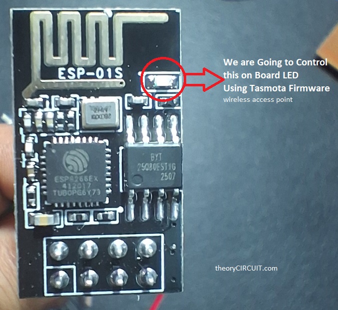
Why the ESP-01?
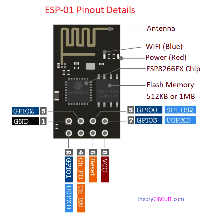
Honestly I thought to use ESP32 board to design a simple locally controlled electric appliance switch, but found the Tasmota supports ESP01 and the ESP01 have enough GPIO pins for my project so it gives me double vibes. And you know the ESP01 is the smallest ESP8266 board you can buy.Here the ESP01 have two GPIO pins, a serial port, an antenna, that’s it. It is tiny, it is cheap, and it is used everywhere. Perfect for a single relay. Perfect for a sensor node. Not great for big projects, you only get GPIO0 and GPIO2 to play with but for a one job smart switch, it’s ideal in my case.
One warning before you buy.
Older ESP01 boards (the blue ones in color) may have only 512KB of flash. Modern TASMOTA needs at least 1MB. If your board memory is too small then the firmware simply won’t fit. The fix is easy just get the ESP-01S, the black one. It has 1MB of flash and works every time.
The Arduino Nano trick I used here!
Here’s the clever part. We don’t want the NANO to run a sketch here. Wire the Arduino nano RESET pin to GND. That holds the ATmega328 chip in reset that is frozen, doing nothing at all. Now the USB-to-serial chip CH340 sitting behind it talks straight through to whatever you wire up. The NANO stops being an Arduino. It becomes a plain CH340 USB-to-TTL adapter for our ESP01 board. No sketch to upload. No drivers to hunt for. Just plug and go. That’s the whole secret. One jumper from RESET to GND, then TX to TX and RX to RX.
Follow the Steps to use Tasmota on ESP01
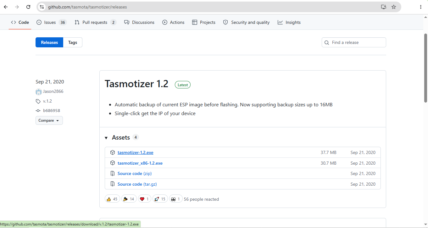
1. Download tasmotizer-1.2
Just download latest Tasmota firmware from
https://github.com/tasmota/tasmotizer/releases
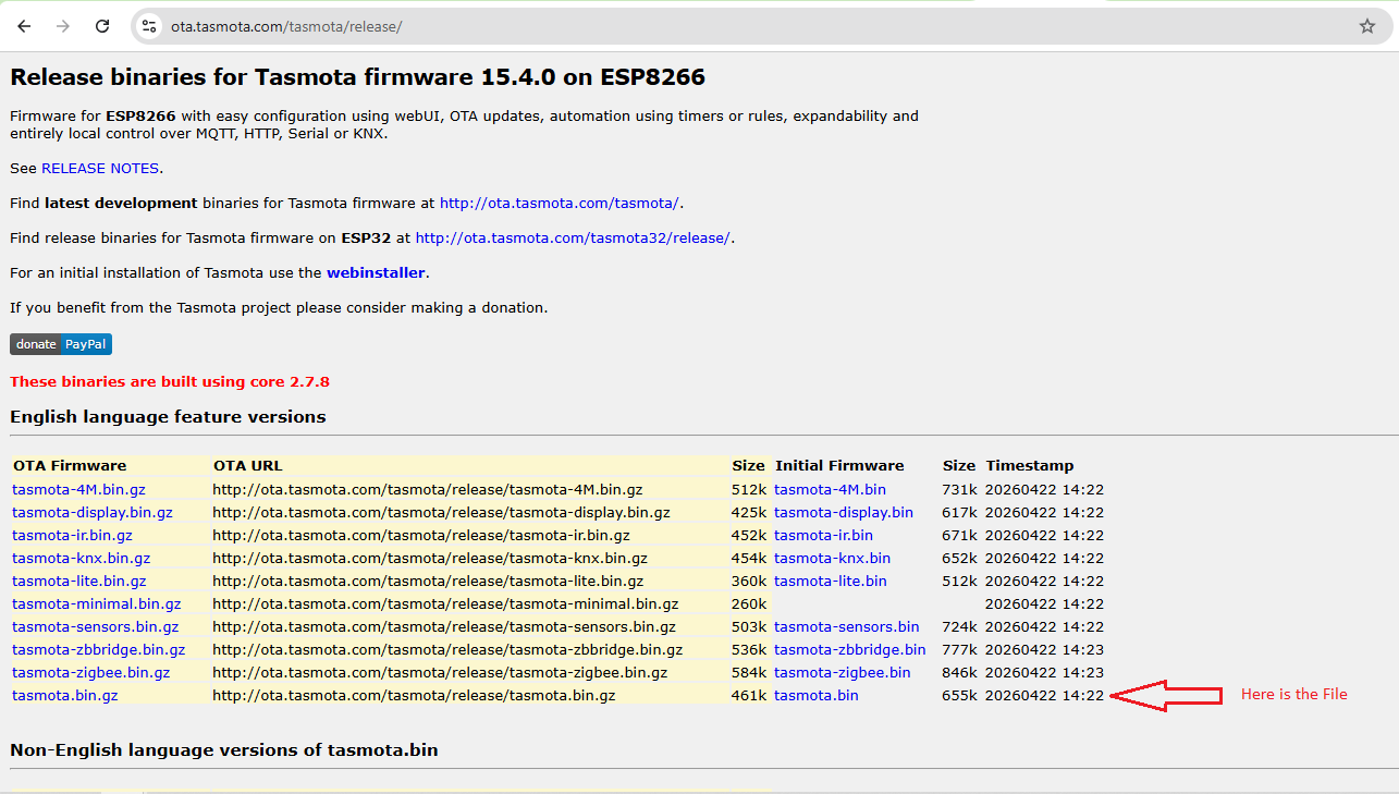
2. Download tasmota.bin
Get the Tasmota bin file and know the download location we have to use it.
https://ota.tasmota.com/tasmota/release/
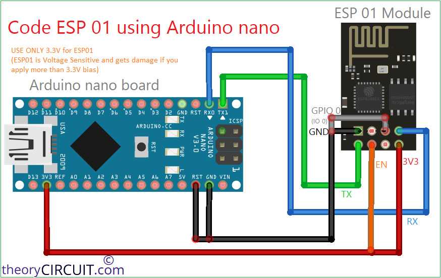
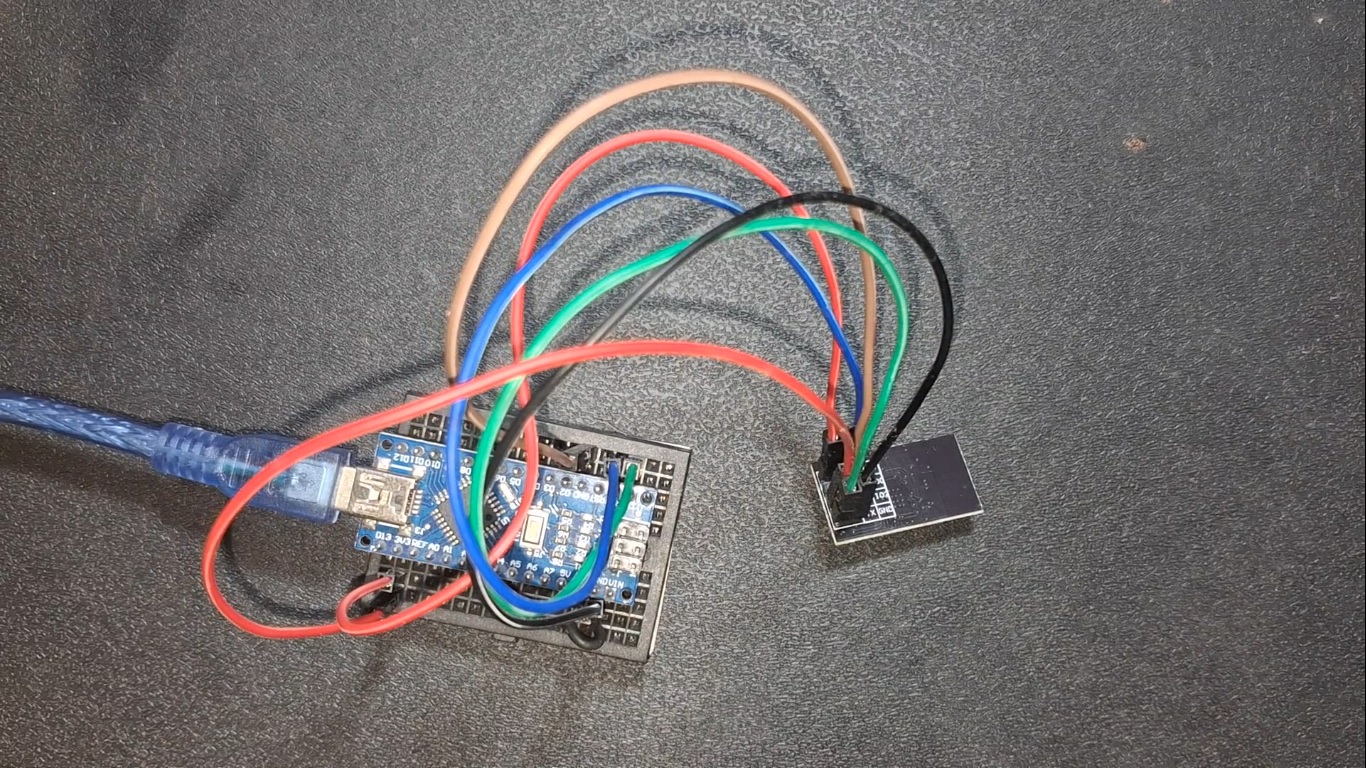
3. Connecting wires with Arduino nano and ESP01
Just follow the wiring diagram and make wiring between Arduino nano and ESP01 board, here the ESP01 board wired in program mode or programming setup.
Wiring Diagram
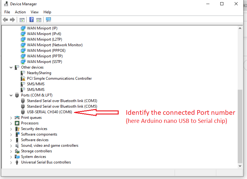
4. Checking port number
After wiring done just connect the Arduino nano with your computer and note down the port number that system allocates to your Arduino board.
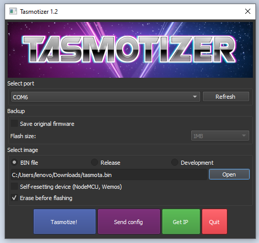
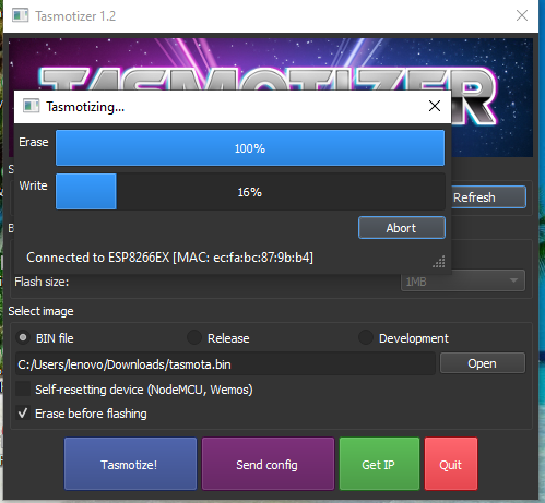
5. Flashing tasmota
Just open the tasmotizer-1.2 execution file and you will see the application window and then select the port and bin file and we are ready to flash the firmware. Just hit the Tasmotize! button and it starts to flash ESP01. After succesfull completion you will the message like “message Process successful! Power cycle the device.”
6. ESP01 to run mode
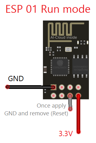
Just make sure 3.3V and GND supply applied to the ESP01 (no other wiring need) for the run mode. Here we are going to use on board LED to experiment Tasmota that is why you see the following wiring., If you want to use any relay or some device then you can make that wiring here in the run mode and make setup in Tasmota local wap web interface.
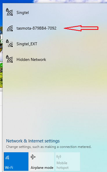
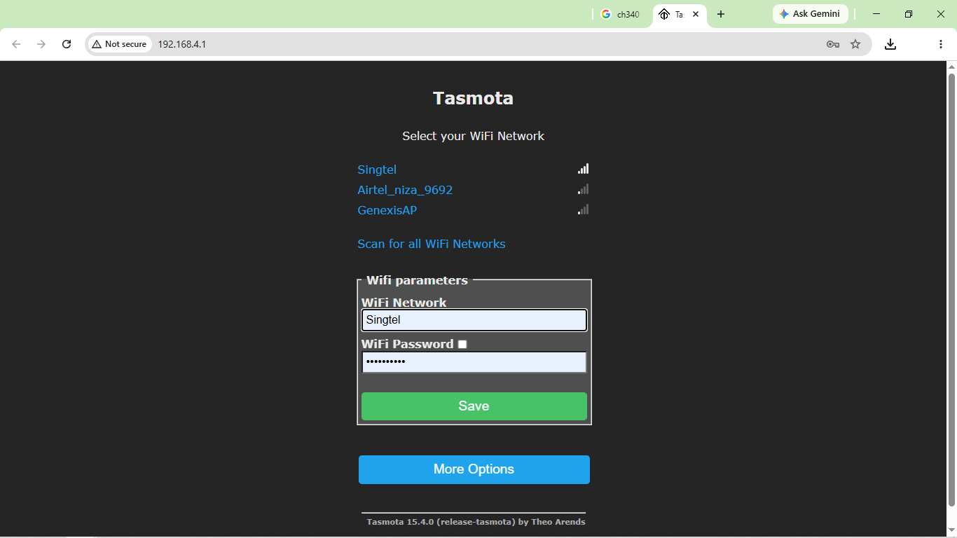
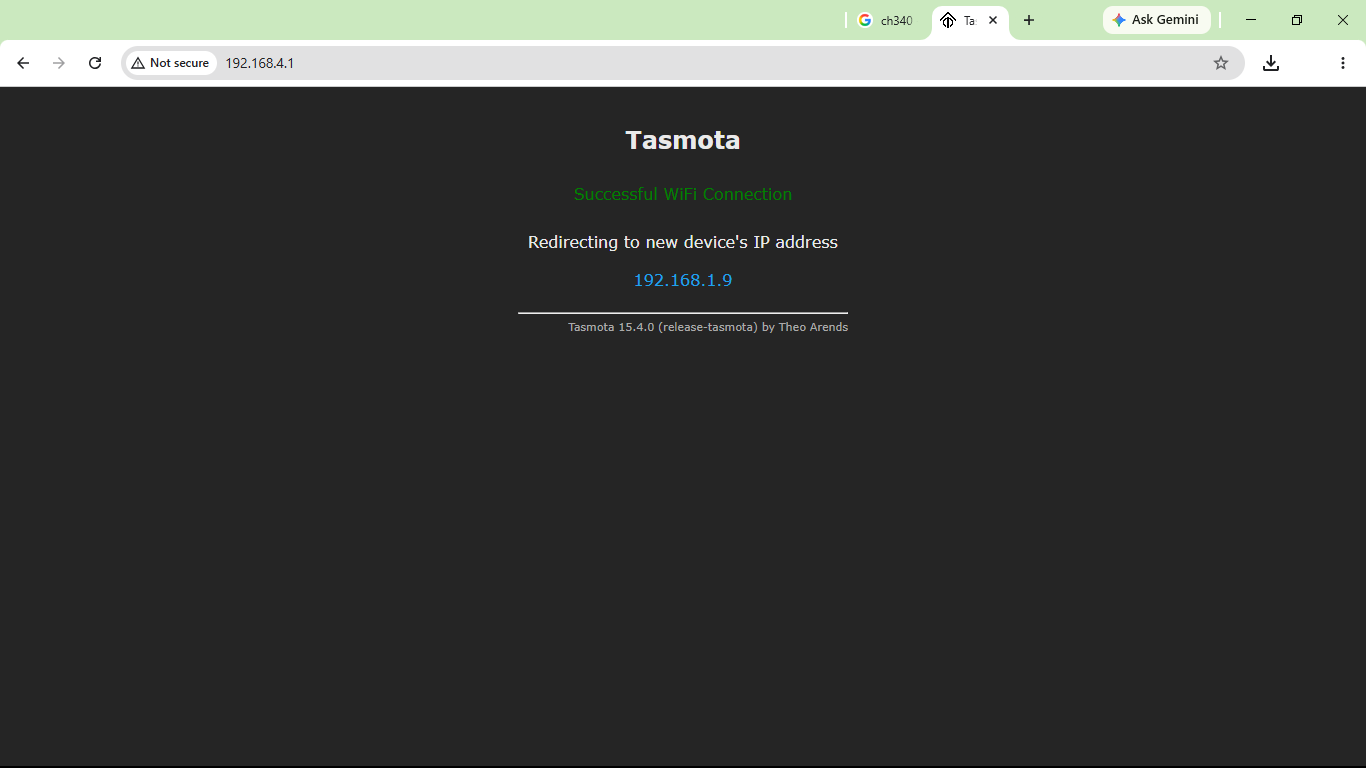
7. ESP01 makes wifi hotspot
When you connect ESP01 in run mode after flashing Tasmota on it, then it will make a WiFi hotspot named “tasmota-xxxxx-xxx” and connect your device to it, after connecting your device with it, open http://192.168.4.1/ and make setup. Here you have to give your WiFi credentials to connect Tasmota enabled ESP01 to your local network. Your wifi credentials won’t go any where it stays in your ESP01. After save your ESP01 with Tasmota connects to your wifi network and shows redirection ip address, if not just click Get IP button on the Tasmotizer app.
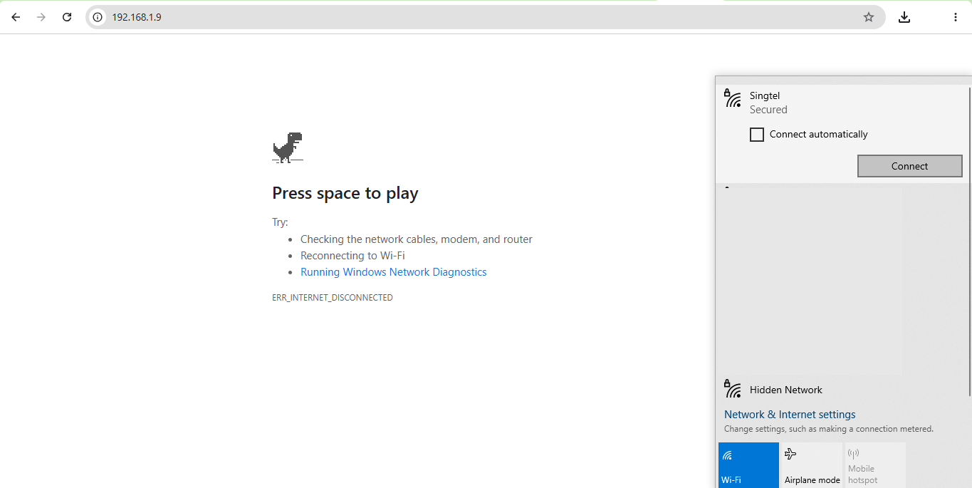
8. Connect your Device to your WiFi
Don’t forget to connect your browsing device in the same local wifi network so that ESP01 and your browsing devices (many can control ESP01) will be in the same network. And then open ESP01 mentioned IP address.
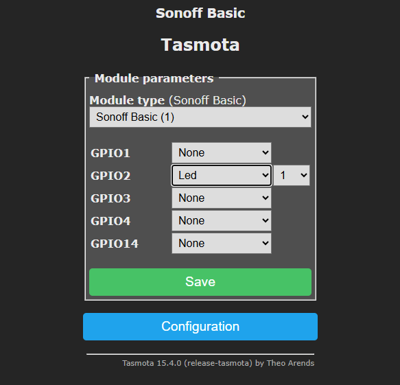
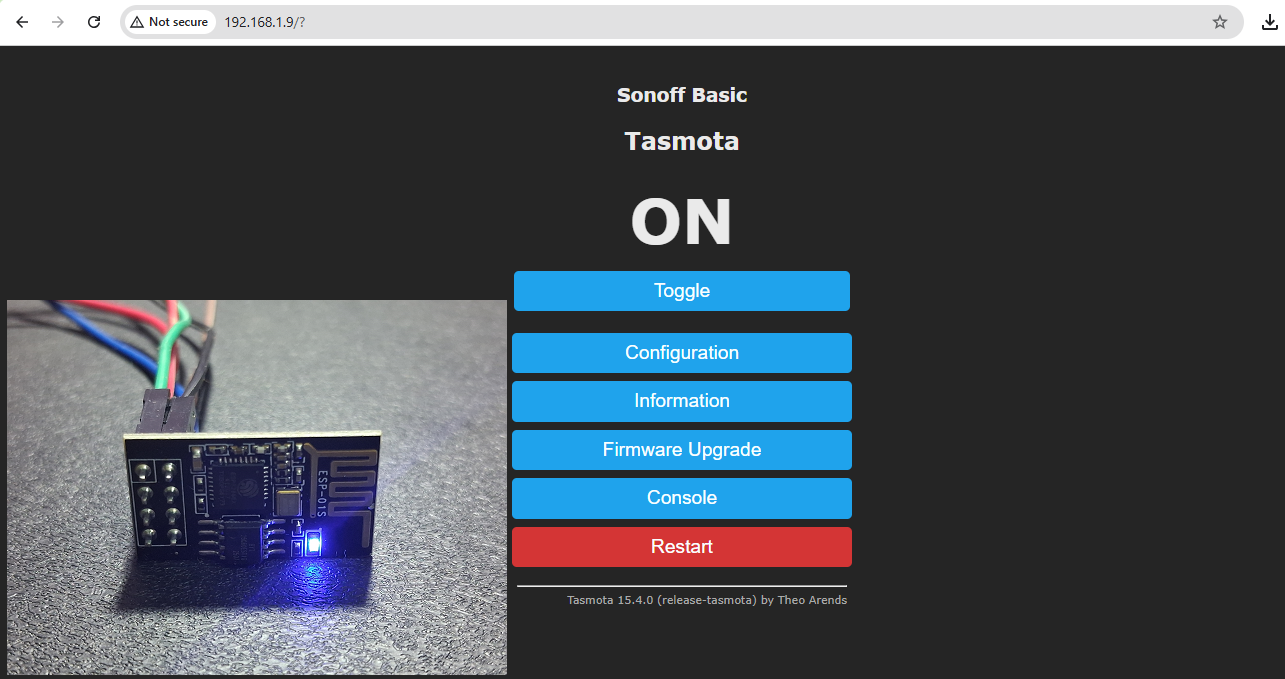
9. Simple Configuration
Here i made simple configuration Sonoff Basic and connected on board LED (GPIO2), choose in the dropdown list and mention 1 for one LED, and save.
10. Your IoT device Ready!
Now you are ready to on or off your device (here on board LED) through IP address of ESP01.
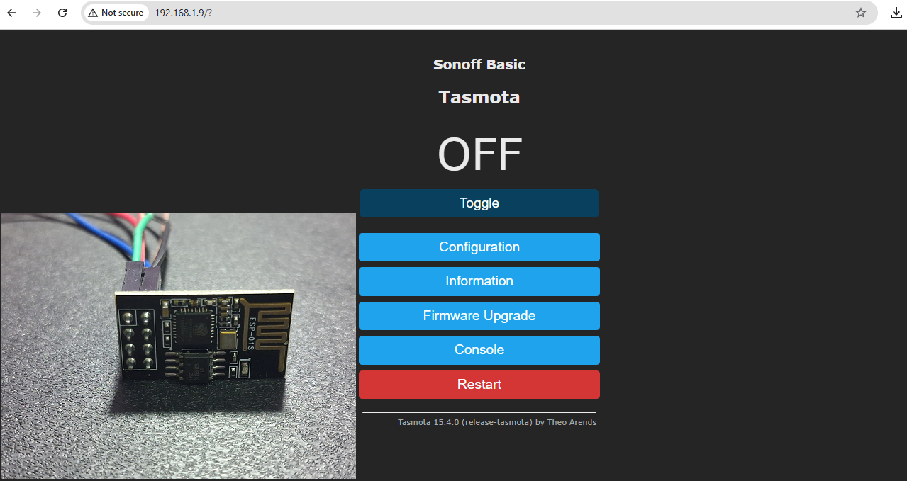
and That’s how you can make simple IoT smart home device.