
Last Updated on March 31, 2024
ADC (Analog to Digital Converter) is a very important element in Embedded Electronics and For Sensors, because most Sensors gives analog output with respect to sensing physical quantity. To store, process and to control these signals from sensor we need to make it digital like binary numbers. So that most Microcontrollers fabricated with Internal ADC device. Like wise Raspberry pi Pico with RP2040 Chip built with 3 × 12-bit ADC and one Internal ADC. This Raspberry Pi Pico ADC Reading Tutorial gives you basic understanding about the Coding and observing ADC in Raspberry pi Pico.
As previously said, the Pico board comes with Three 12 bit ADC Channels, Those can be accessed with,
| Hardware pin | GPIO Pin | ADC Channel Name |
| Pin 31 | GPIO26 | ADC0 |
| Pin 32 | GPIO27 | ADC1 |
| Pin 34 | GPIO28 | ADC2 |
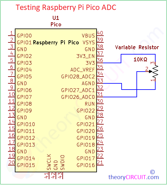
Hardware pin 33 Can be used and AGND (Ground for ADC) and Hardware pin 35 Can be used as ADC_VREF, if reference voltage need. In the following circuit we have used ADC0 Channel and AGND, for power supply, we used Hardware pin 36 that is 3V3(OUT).
If you are new to Raspberry pi Pico, then read Easy Way to Start Programming with Raspberry Pi Pico.
Wiring
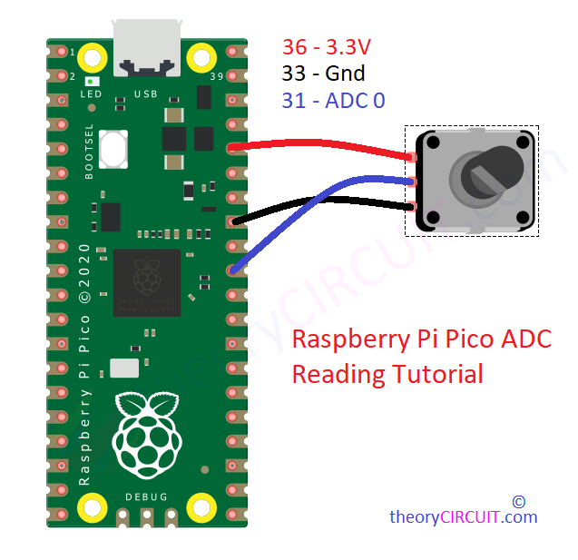
Pico Board Connection
Schematic Diagram
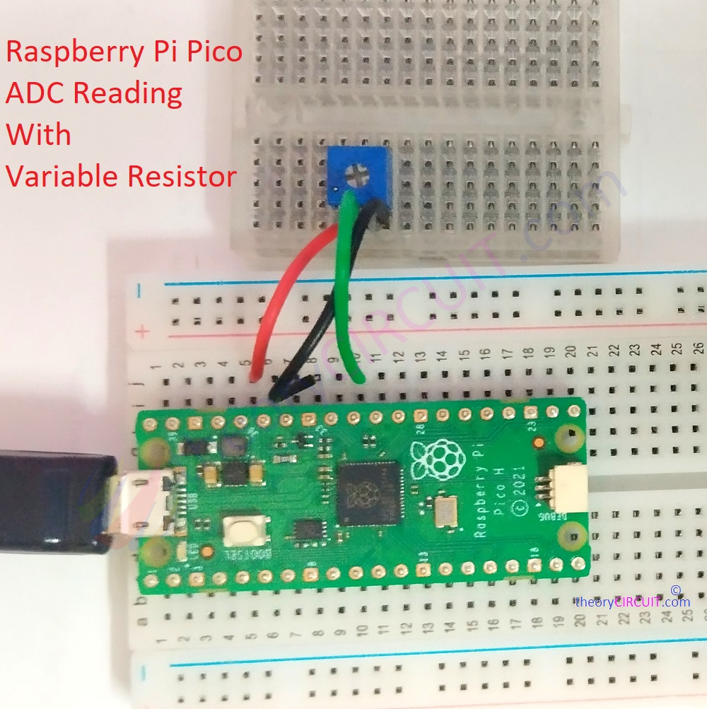
Components Required
- Raspberry pi Pico
- Variable Resistor 10KΩ
- Micro B USB Cable
- Computer with Thonny IDE
Construction & Working
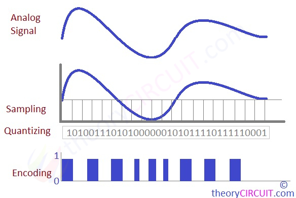
Before using ADC in Pico board, let us recall about Analog to Digital Converter operation.
ADC is a Crucial component in most electronic systems, it converters Continuous Analog signal into Digital Data. For Sensing Physical quantity or to interface any analog device with Microcontroller or Digital signal Processors, ADC will be the Interfacing element. Basic Operation of ADC is ‘Sampling the Analog input Signal at discrete intervals and Quantizing it into Digital values’. Most ADC makes Sampling, Quantization and Encoding and final result will be Binary representation of input Analog Signal from sensor or source.
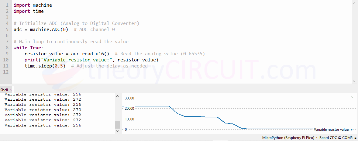
We are not going to do any Encoding, we just receive analog voltage from variable Resistor and Sense that voltage with the help of Internal ADC (channel ADC0) and print digital Value. Make hardware connections as mentioned in the wiring diagram. Then use Thonny IDE to upload the following Code.
After that you can receive output like the following, you can adjust the variable Resistor value and observe the changes in digital value.
By this way can connect any three wire analog output sensor and observe digital value by adding extra code we can create conditions and output actuator controlling.