Last Updated on March 16, 2024
Colorful LED light applications are not limited, here is the Simple RGB LED Interfacing with Raspberry Pi Pico to learn about controlling of RGB LED through micropython programming. When we use Astable multivibrator or some analog circuit to bias RGB LEDs we get few modes of operation like blinking at different speed. While we use Microcontrollers to drive RGB LEDs we can make many patterns and designs through programming.
As we know LEDs are revolutionary invention in the history of mankind, and we use LEDs because of its Color Range, Low Power consumption and Fast switching response. RGB LED is a component and Red, Green, Blue (Primary Colors) individual semiconductor die placed inside a epoxy case. Depends on the Common pin RGB LED is classified into two types, 1. Common Anode. 2. Common Cathode. It requires minimum forward Voltage between 2V to 3.3V. Through hole RGB LED will have four pins and lengthier one acts as Common pin. All LED semiconductor inside will glow only in forward bias that is Positive supply for Anode and Negative Supply for cathode. Forward bias Resistor is important to protect LED from over current flow.


Check the RGB LED pins and its color (3V + 220Ω Resistor in FB) before using it in a project.
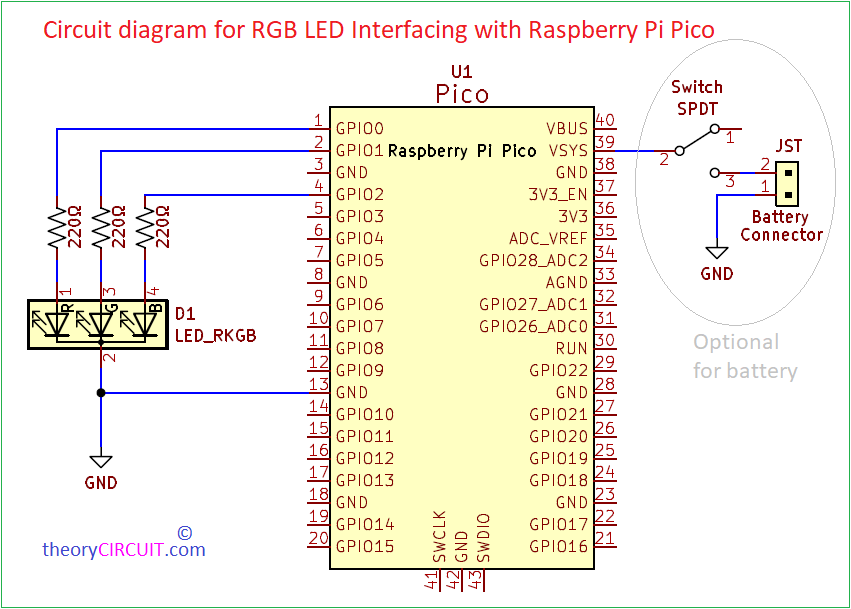
Circuit Diagram
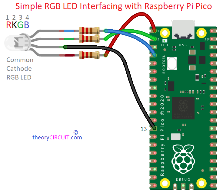
Hardware Wire Connection
Components List
- Raspberry pi Pico
- RGB LED (here we used Common Cathode RKGB) LED
- Resistor 220Ω
- Breadboard
- Connecting Wires
- Computer + Micro USB B data Cable
Construction & Working
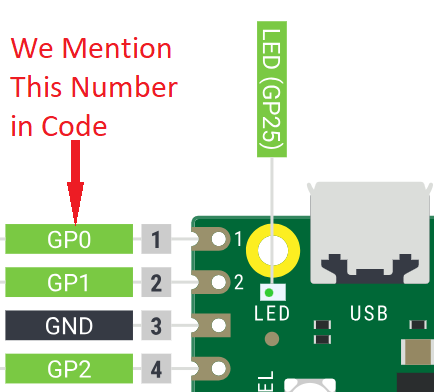
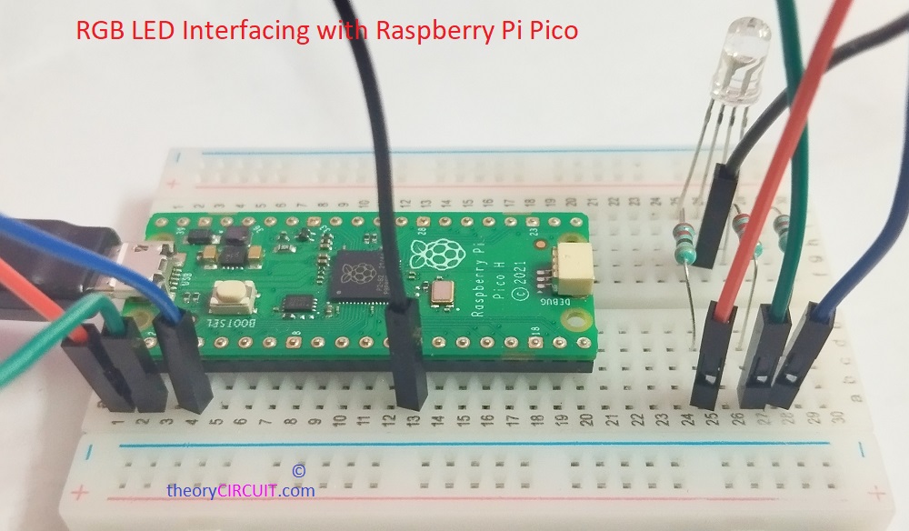
Place Raspberry Pi Pico in a breadboard and ensure proper placement and continuty in contact terminals of breadboard. As we know depends on the Raspberry pi Pico Pinout we make connections and program. Here we taken GP0, GP1 and GP2 pins for Red, Green and Blue terminals in RGB LED. So we have to import pins as 0, 1 and 2 pin micropython code. In Pico board these pins are counted as Pin1, Pin2, Pin4 and we don’t need it in code.
Connect 220Ω Resistor for each pins of RGB LED other than common pin (here GND – Common Cathode). After Completing Hardware Setup, now we have to make micropython code and make it run, after connecting Raspberry Pi Pico with USB Port of Computer.
- If you are new to Raspberry Pi Pico Get Started Here.
After Completing Hardware setup for Pico and RGB LED it may look like this!
MicroPython Code Example for Raspberry Pi Pico RGB LED
import machine
import utime

# Define pins for RGB LED (change as per your wiring)
red_pin = machine.Pin(0)
green_pin = machine.Pin(1)
blue_pin = machine.Pin(2)

# Initialize PWM for each pin with a frequency of 1000 Hz
red_pwm = machine.PWM(red_pin, freq=1000)
green_pwm = machine.PWM(green_pin, freq=1000)
blue_pwm = machine.PWM(blue_pin, freq=1000)

# Function to fade in and out
def fade_in_out(pwm, delay):
    # Fade in
    for duty in range(0, 65535, 256):
        pwm.duty_u16(duty)
        utime.sleep_ms(delay)
    # Fade out
    for duty in range(65535, -1, -256):
        pwm.duty_u16(duty)
        utime.sleep_ms(delay)

# Main loop
while True:
    # Fade in and out for each color channel
    fade_in_out(red_pwm, 5)
    fade_in_out(green_pwm, 5)
    fade_in_out(blue_pwm, 5)
After Coding and Run you will get Result like this.