
Last Updated on March 31, 2024
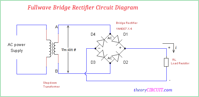
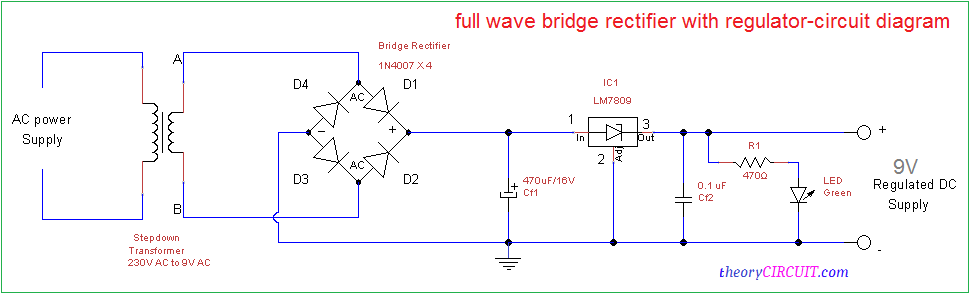
Full wave bridge rectifier circuit diagram is widely used in AC to DC converter and DC circuit designs, this full wave rectifier called as bridge rectifier due to it shape. It contains four diodes arranged in a bridge format and an ordinary step down transformer.
We know the most electronic devices or circuit needs DC power for their proper operation. But we get AC (Alternating Current) supply in order to convert it into DC power supply we need Rectifier circuits, there are three way to design a rectifier, 1. Half wave rectifier, 2.Full wave rectifier 3. Bridge rectifier overall these three bridge rectifier gives better efficiency and ripple free DC.
Circuit diagram
Working details of Bridge Rectifier
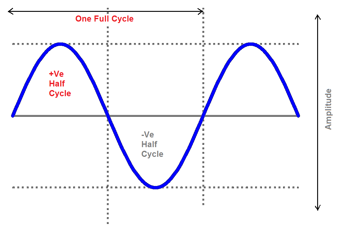
The step down transformer reduces the High voltage AC into Low amplitude AC supply and that is also in SINE form (Positive and Negative cycles), during the positive cycle of the input signal terminal A is positive with respect to terminal B. Here the current flows through D1 diode and RL and then D3 diode finally it reaches the terminal B. During this cycle Diodes D2 and D4 are not conducting any current supply.
During the negative cycle of the input, terminal B is positive with respect to terminal A and now the current flows through D2 diode, RL and D4 diode finally it reaches the terminal A. During this cycle diodes D1 and D3 are not conducting. Hence for both positive and negative cycles RL gets current flow so its called as full wave bridge rectifier.
Input and Output Waveforms
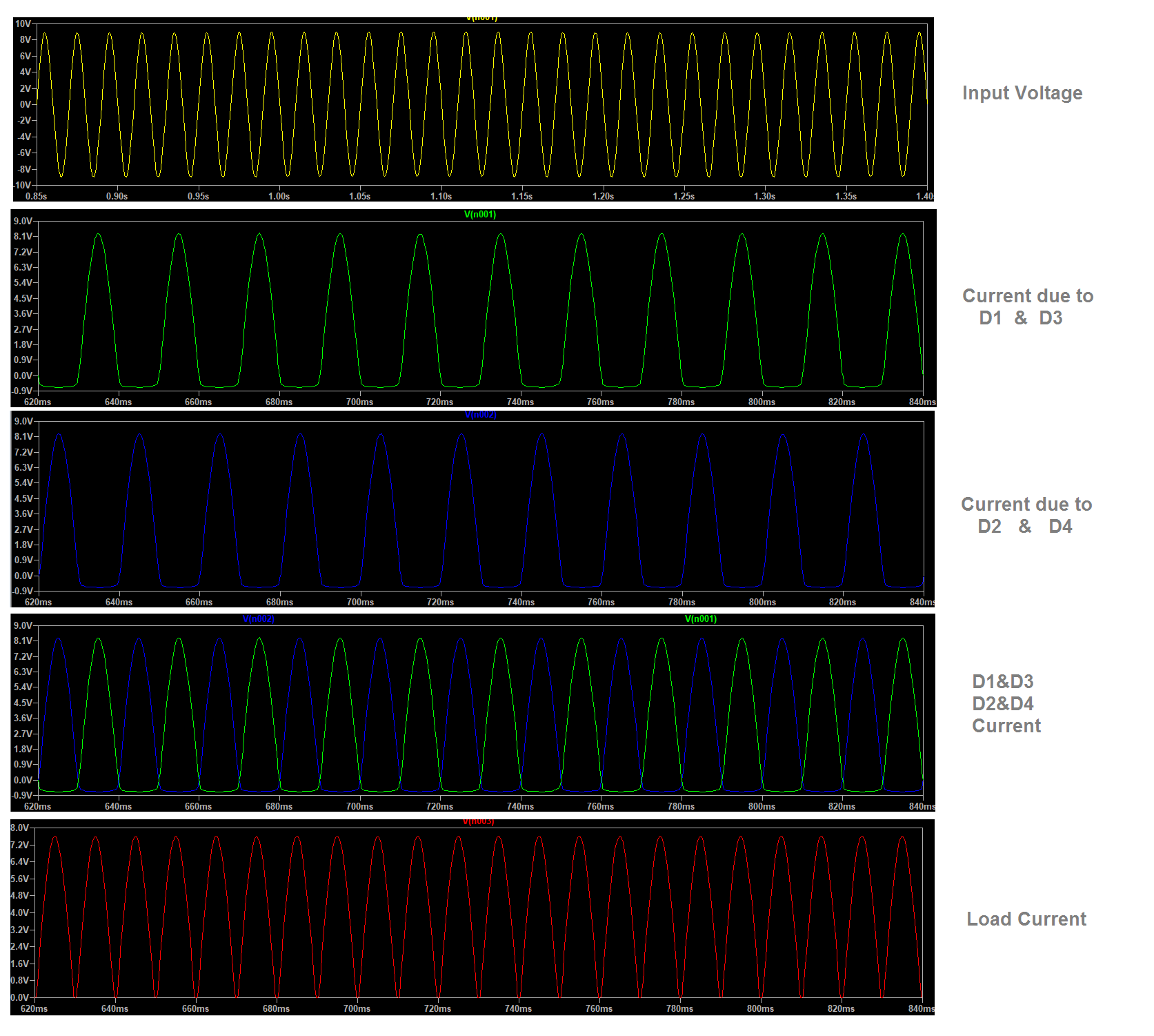
The first wave represents the input voltage and then each diode output current and voltage plotted, finally the load current appeared on load resistor RL, when we use bridge rectifier we can get continuous load current and voltage.
Some Characteristics for Reference
- Efficiency:- 81.6%
- DC output Current:- 2Im/Π
- RMS Current:- Im/√2
- Peak Inverse Voltage:- Vm
- Ripple factor:- 0.483
- Ripple frequency:- 2fin
- Transformer Utilization Factor:- 0.812
Bridge Rectifier Application prototypes
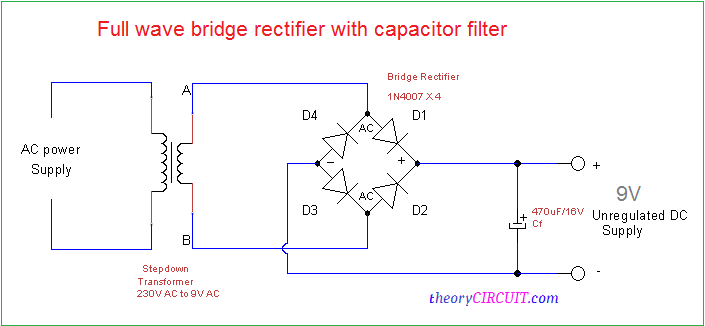
Bridge Rectifier IC

It is very easy to find bridge rectifier IC depends on your current and voltage requirements or you can construct your own with four diodes.