
Last Updated on March 25, 2024
For all kind of Colorful LED light and decoration we can use only one type of device that is WS2812B RGB LED or Neopixel LED, it comes LED comes in different packages like 5050, 2020 etc.., WS2812B is the upgraded version of WS2812 series. It can be easily controlled by single wire data input and can be extended to long distance, when we use proper power supply. In this tutorial we are going to experiment Interfacing WS2812B Neopixel LED Strip with Raspberry pi Pico.
We have taken 8 bit LED strip that contains eight individual WS2812B LED, and tried three different patterns of Light effect and got amazing result. Lets get started!
Before that if you are new to Raspberry pi Pico, you have to do some presetting work and installations, refer here.
WS2812B Neopixel LED Module Pinout
In recent days Neopixel or WS2812B series RGB LEDs are getting more attention from lighting experts, Engineers and fashion designers. Either in 5050 or 2020 package this device have Red, Green and Blue LEDs attached with WS2812B chip. You can see that chip through transparent epoxy layer (black color chip with connected strings). This chip is responsible for controlling RGB LEDs and it controls through single Data input method called 1 wire NZR communication. This tiny LED or Neopixel requires no external components and makes 16777216 colors with brightness control. Consumes very low current during its operation.
Wiring
Circuit Diagram
Components Required
- Raspberry pi Pico with data cable
- WS2812B LED strip 8 bit
- Computer for coding
Preparing WS2812B LED Strip
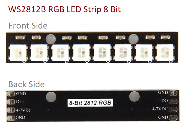
WS2812B RGB LED strip 8 bit may look like the above and you have to solder wire to connect it to the Raspberry pi or with any microcontrollers. When you are using only one strip, DO (Data out) pin will not be required (This is for to connect next strip DI pin). We are going to use DI pin side, Use black from ribbon wire to solder with GND and use Red wire to solder with 4-7 VDC pin and use brown (your wish) wire to solder with DI pin. If you are new to Soldering refer here.
Connection & Working
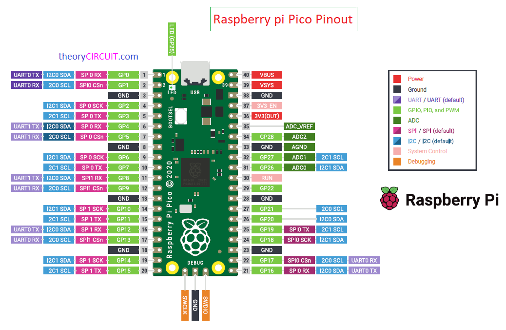
If you are using LED strip with more than 12 LEDs then you have to use external power supply (5V DC with required current output), for experiment we use 8 LEDs strip so there is no need for external power supply, 4-7 VDC pin from strip is directly connected with VBUS pin of Pico and GND to any GND pin of Raspberry pi Pico then DI (Data Input Pin) is connected with GP6 (terminal 9) Pin. You can connect DI to any convenient pin in pico.
After completing wiring connect the Pico to computer through USB cable and open Thonny Python IDE then Run the following code to observe light effect.
1. RGB Blink Python Code
Output In Full Brightness!
2. To Control Brightness
def blink_leds(color, duration):
set_led_color(color)
updatePixel(1) # 0 to 1 to change brightness
time.sleep(duration)
set_led_color((0, 0, 0)) # Turn off LEDs
updatePixel(1) # 0 to 1 to change brightness
time.sleep(duration)
We can change the brightness by changing number from 0 to 1 in updatePixel(1) line, for an example updatePixel(0.01) gives lowest possible brightness and updatePixel(0.5) gives half brightness. after changing code the result will be,
3. WS2812B Running LED effect code for Raspberry pi Pico
Output
4. WS2812B Rainbow Effect Code Raspberry pi Pico
Output Rainbow Effect light
Try it and ask in comment if you have any doubts!
how to do this with usb-c power delivery with other rp2040 variants? I’m trying to build usb-c powered ws2812 but can’t find anything usefull every says get external power supply …. why not using those 25w wall chargers and do it with usb-c