Last Updated on December 12, 2024
ADC (Analog to Digital Converter) plays important role in every embedded electronics and microcontroller based system. For to take, process and store or react based on Analog signal (physical quantity to electric signal through sensor) we need ADC. It converts continuous signal into a digital signal (a discrete set of numerical values). ADCs are essential in modern electronics. Here the following ADC Calculator will give you digital output value and binary value depends on your input and will help you in many aspect to choose ADC.
ADC Calculator
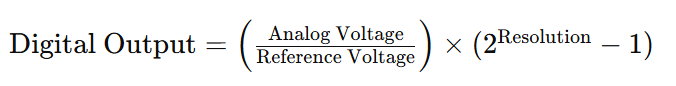
This Analog to Digital Converter Calculator works with following formulat.
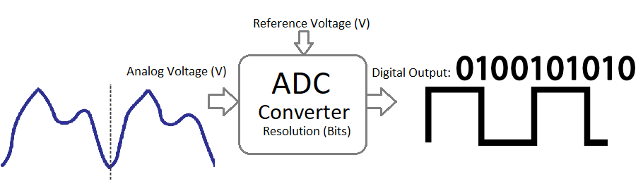
Almost every ADC requires three basic inputs to convert Analog signal into digital signal. 1. Analog Voltage (V) Input, 2. Reference Voltage (V), 3. Resolution (Bits).
When we design embedded electronic system with microcontroller and sensor, we need to understand the deployment area and the required level of ADC Resolution to pick all the changes through sensor. This calculator will help you to decide those factors.