
Last Updated on March 16, 2024
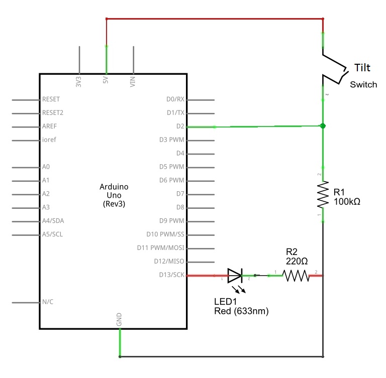
The small inexpensive easy to use sensor, it allows you to detect orientation or inclination. By connecting this tilt sensor with Arduino we can control LED, buzzer or other output devices. Here we interfaced tilt sensor with Arduino board and LED as output indicator, remember to connect 10KΩ bias resistor between ground (GND) and one terminal of tilt sensor that is connected to Arduino digital input pin.
What is Tilt Switch or Sensor?
A tilt sensor is like a smart button that senses when an object tilts. It’s similar to how pushing a button works, but with a different mechanism. Think of it as an eco friendly alternative to mercury switches. Inside the sensor, there’s a tiny ball that moves, connecting or disconnecting two pins when the sensor tilts at a specific angle. It is a simple yet effective way to detect movement in electronic devices.
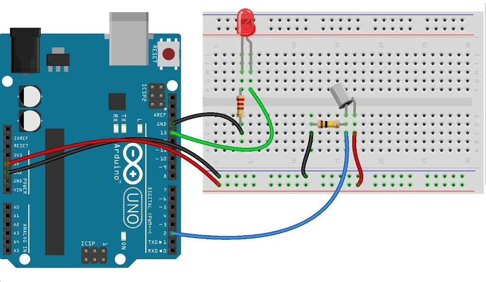
Circuit diagram
In this sensor two conducting poles placed and the mass roller placed between these two pole elements. When the orientation of sensor changes to downwards the mass role shorts the two pole and act as a switch throw.
Arduino Tilt Switch sensor sketch code
//*www.theorycircuit.com*
int SensorPin = 2;
int LEDPin = 13;
int LEDstate = HIGH;
int reading;
int previous = LOW;
long time = 0;
long debounce = 50;
void setup()
{
pinMode(SensorPin, INPUT);
digitalWrite(SensorPin, HIGH);
pinMode(LEDPin, OUTPUT);
}
void loop()
{
int switchstate;
reading = digitalRead(SensorPin);
if (reading != previous) {
time = millis();
}
if ((millis() - time) > debounce) {
switchstate = reading;
if (switchstate == HIGH) {
 LEDstate = LOW;
}
else
{
LEDstate = HIGH;
}
}
digitalWrite(LEDPin, LEDstate);
previous = reading;
}
This Arduino code reads tilt switch sensor position and indicates its status through LED connected at Digital pin 13. You can use any output actuator to be controlled by Tilt switch sensor.
Components List
| S.No | Name | Quantity |
| 1. | Arduino uno | 1 |
| 2. | Tilt switch sensor | 1 |
| 3. | LED | Red 1 |
| 4. | Resistor 220 Ω 100 KΩ | 1 1 |
| 5. | Connecting wires | as required |