Last Updated on May 25, 2026
Motion sensing projects are one of the easiest and most useful do it your self electronics projects for beginners. Normally people use Arduino UNO boards for motion detection during prototype, but for compact and low cost applications, we can’t use whole Arduino uno or other boards, here the Digispark ATtiny85 board enters with possibility of Arduino Coding, Yes you can Program ATtiny85 microcontroller with Arduino IDE, If you are new to use ATtiny85 Digispark read here for to get started.
We know that Digispark board is tiny, USB programmable and perfect for small automation systems using ATtiny85 Microcontroller. Here we are going to interface a PIR that is Passive Infrared sensor with the Digispark ATtiny85 board and build a simple motion detection Indicator with on board LED and PIR Sensor Motion Activated RGB Animation using 4×4 WS2812B.
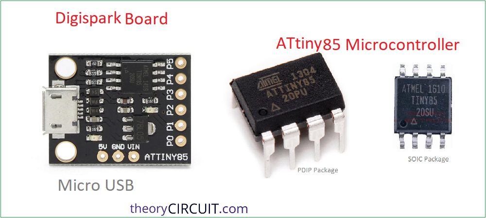
ATtiny85 Microcontroller
You may heared about small microcontrollers but did you tried one, here is the ATtiny85, powerful 8 bit AVR microcontroller widely used in compact embedded electronics projects. Even though it comes in a tiny 8 pin package, it can handle digital I/O, PWM, ADC, timers, and low power applications very efficiently with battery bias. I personally like using ATtiny85 for small automation and sensor based projects because it reduces circuit size, power consumption, and overall cost compared to larger Microcontrollers with unused features. It is also compatible with Arduino IDE, when we use it with USB bootloader called Micronucleus which makes programming much easier for beginners as well as embedded developers.
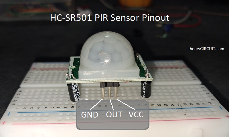
HC-SR501 PIR Sensor
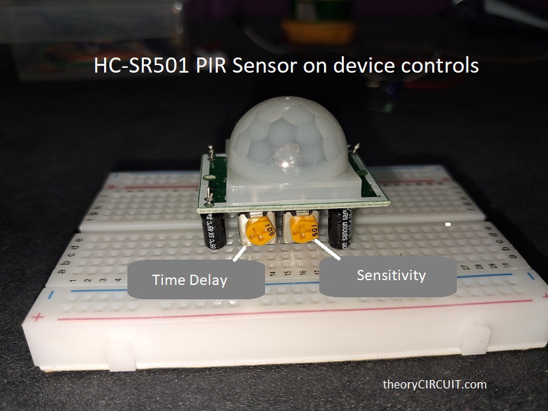
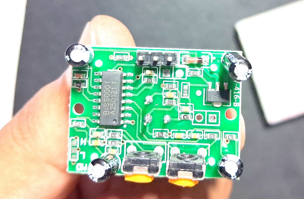
HC-SR501 PIR Sensor is a sensor that detects Infrared Radiation produced by heat from human body, animal or moving Soldering iron! It is a popular motion detection sensor module used by most of hobbist and electronics makers to make detection and automation projects. It works by detecting changes in infrared radiation emitted by humans or animals and provides a digital output whenever motion is detected. One thing I like about this module is that it already contains built in on board signal conditioning circuit in the back PCB, which makes interfacing very easy with microcontrollers like Arduino, ESP32, and ATtiny85 and also standalone indicator. The sensor also includes adjustable sensitivity and delay time controls that you can see on backside of plastic sense area, so it is suitable for applications such as automatic lighting, security alarms, smart home systems, and occupancy detection projects.
Important steps to follow while coding ATtiny85 Digispark board using Arduino IDE.
1. Open Arduino IDE (Do not Connect ATtiny85 board with computer) then Go to File > Preferences and then in Additional Boards Manager URL paste the given JSON link and click ok.
https://raw.githubusercontent.com/digistump/arduino-boards-index/master/package_digistump_index.json2. Install Digistump AVR Boards package (as we do when we use new boards in the Arduino IDE, Boards Manager and Search for digistump and Install)
3. Select Board → Digispark (Default – 16.5mhz)
4. Write code then Click Upload (without connecting the ATtiny85 Digispark board with computer)
5. After compilation completes, see the output terminal to show “Plug in device now… (will timeout in 60 seconds)” now connect ATtiny85 board with computer.
code upload starts automatically.
Circuit diagram for Motion Detection Indicator
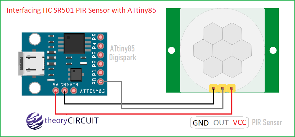
| HC-SR501 Pin | Digispark Pin | Notes |
|---|---|---|
| VCC | 5V | Digispark onboard 5V pin |
| GND | GND | Common ground |
| OUT | P0 | Optional – Digital input with 10kΩ pull-down to GND |
Connect ATtiny85 Digispark board and PIR sensor module as shown in the circuit diagram then upload the following code through Arduino IDE.
/*Interfacing HC SR501 PIR Sensor with ATtiny85-theoryCIRCUIT.com*/
#define PIR_PIN 0     // Digispark P0
#define LED_PIN 1     // Digispark P1

void setup()
{
    pinMode(PIR_PIN, INPUT);
    pinMode(LED_PIN, OUTPUT);
}

void loop()
{
    int motion = digitalRead(PIR_PIN);

    if(motion == HIGH)
    {
        digitalWrite(LED_PIN, HIGH);
    }
    else
    {
        digitalWrite(LED_PIN, LOW);
    }

    delay(100);
}
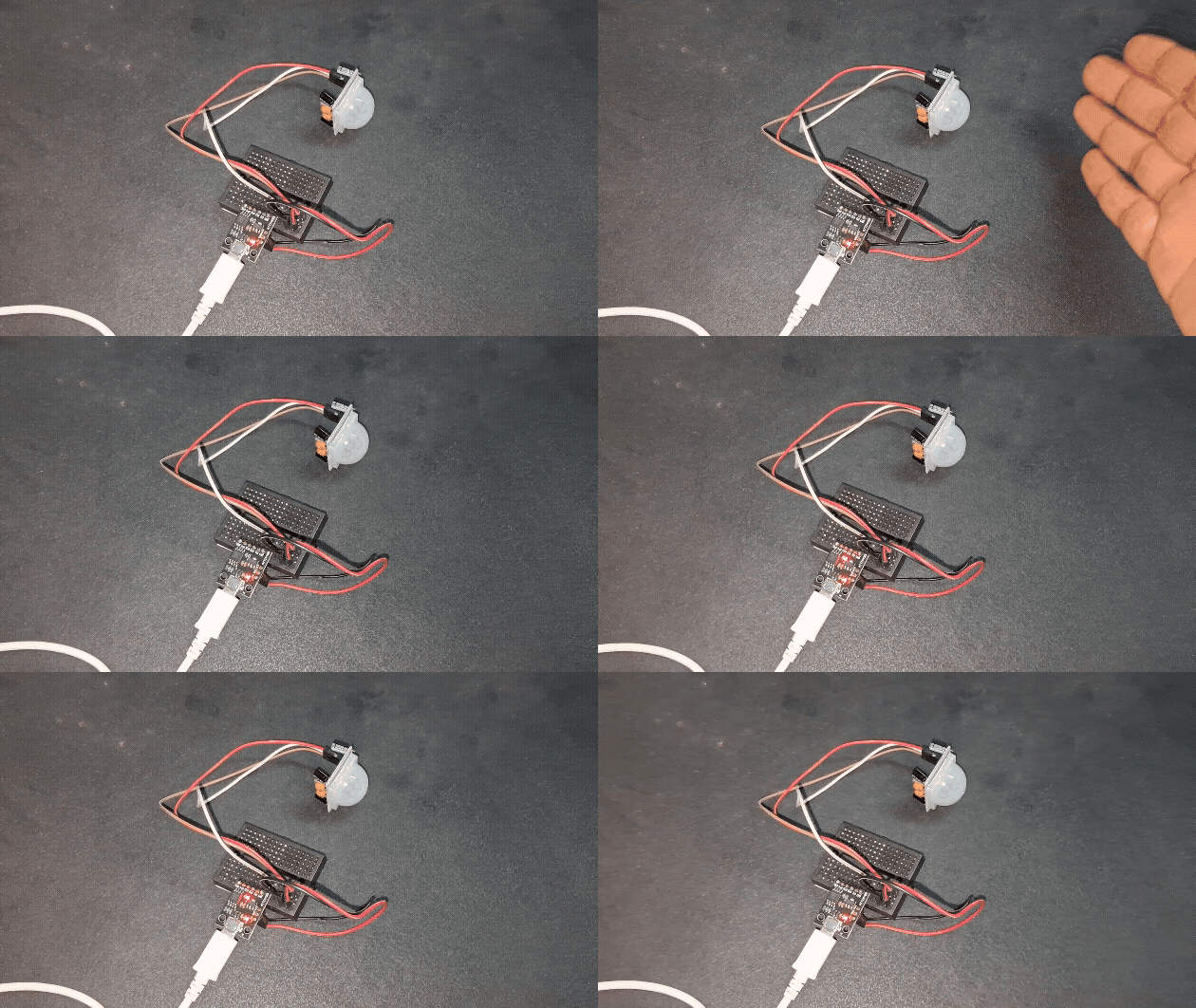
After uploading the code you have to wait for 30 seconds for PIR sensor warmup then you can see the Motion detection indication through on board LED of Digispark board.
PIR Sensor Motion Activated RGB Animation using 4×4 WS2812B and ATtiny85
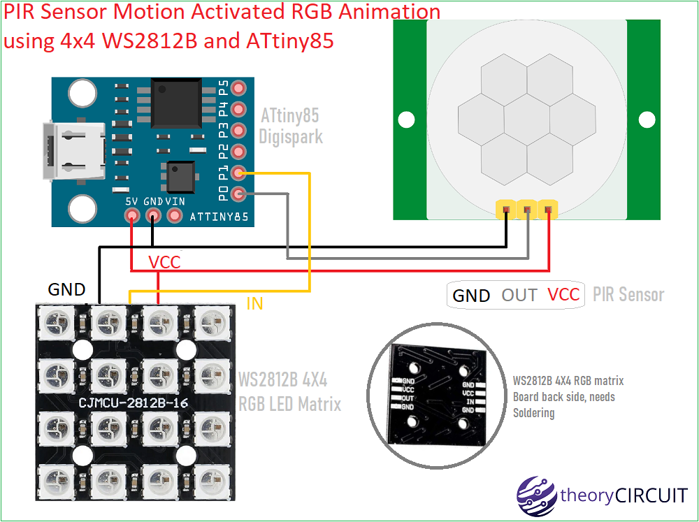
| HC-SR501 Pin | Digispark Pin | WS2812B 4X4 Pin | Notes |
|---|---|---|---|
| VCC | 5V | VCC | Digispark onboard 5V pin |
| GND | GND | GND | Common ground |
| OUT | P0 | ——— | Optional – Digital input with 10kΩ pull-down to GND |
| ——— | P1 | IN | Control signal to WS2812B RGB LED from ATtiny85 |
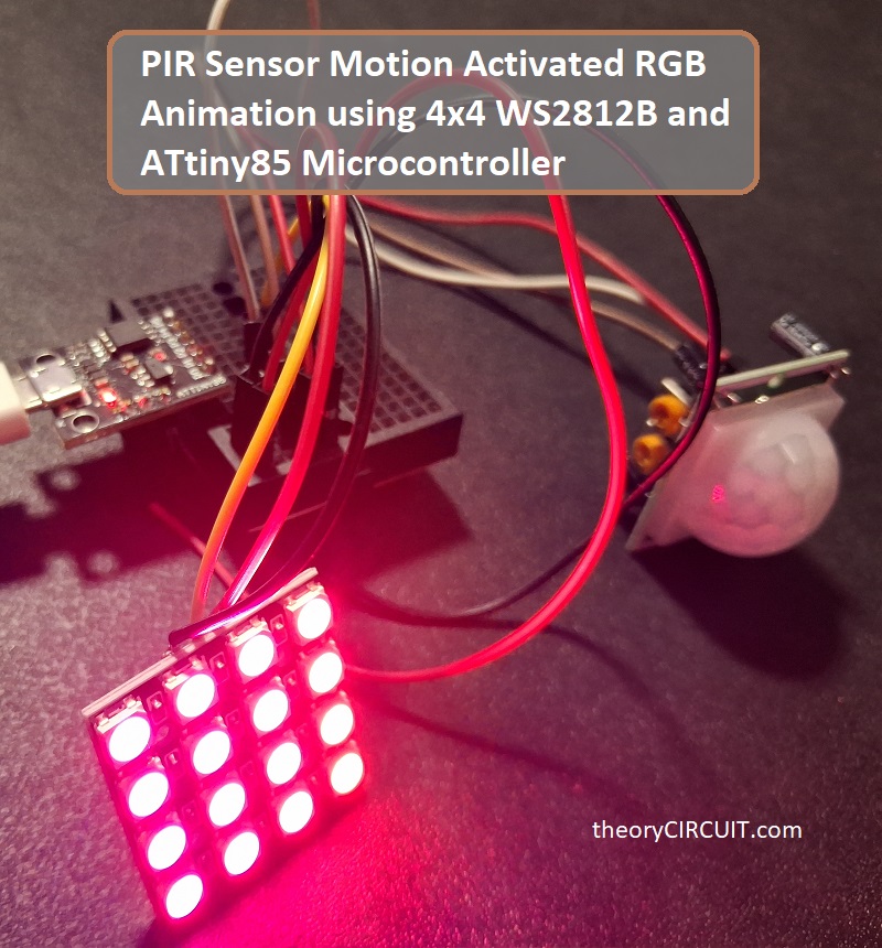
Code for to Animate WS2812B 4X4 RGB LED using PIR sensor and ATtiny85 Microcontroller
/*PIR Sensor Motion Activated RGB Animation using 4x4 WS2812B and ATtiny85 - theoryCIRCUIT*/
#include <Adafruit_NeoPixel.h>

#define LED_PIN    1      // WS2812B connected to P1
#define PIR_PIN    0      // PIR OUT connected to P0
#define NUM_LEDS   16

Adafruit_NeoPixel matrix(NUM_LEDS, LED_PIN, NEO_GRB + NEO_KHZ800);

bool motionDetected = false;

void setup() {
  pinMode(PIR_PIN, INPUT);
  matrix.begin();
  matrix.show(); // Turn OFF all LEDs
}

void loop() {
  int pirState = digitalRead(PIR_PIN);
  if (pirState == HIGH) {
    motionAnimation();
  } else {
    turnOffMatrix();
  }
}

void motionAnimation() {

  // Rainbow wipe animation

  for (int j = 0; j < 256; j += 5) {

    for (int i = 0; i < NUM_LEDS; i++) {
      matrix.setPixelColor(i, wheel((i + j) & 255));
    }

    matrix.show();
    delay(30);

    // Stop animation if no motion
    if (digitalRead(PIR_PIN) == LOW) {
      turnOffMatrix();
      return;
    }
  }
}

void turnOffMatrix() {

  for (int i = 0; i < NUM_LEDS; i++) {
    matrix.setPixelColor(i, 0);
  }
  matrix.show();
}

uint32_t wheel(byte pos) {
  pos = 255 - pos;
  if (pos < 85) {
    return matrix.Color(255 - pos * 3, 0, pos * 3);
  }

  if (pos < 170) {
    pos -= 85;
    return matrix.Color(0, pos * 3, 255 - pos * 3);
  }

  pos -= 170;

  return matrix.Color(pos * 3, 255 - pos * 3, 0);

}
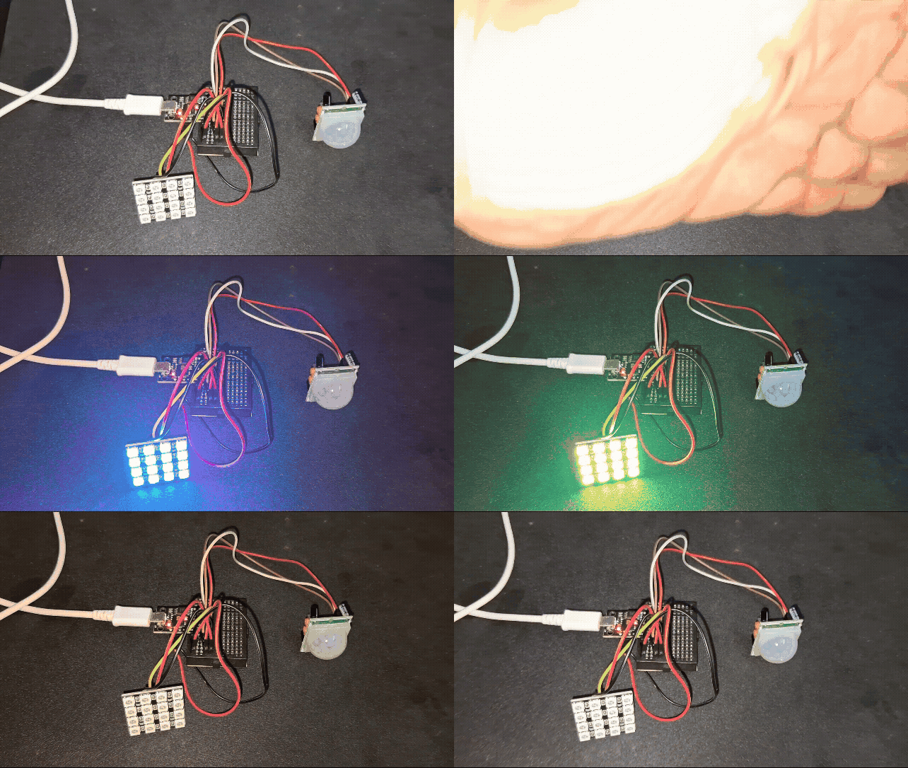
Output Animation