Last Updated on March 25, 2024
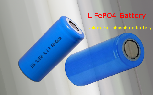
Lithium iron phosphate battery as known as LiFePo4 battery, Due to its lower cost, high safety, low toxicity, long cycle life and other factors, LiFePo4 batteries are used in vehicle, utility scale stationary applications, backup power and portable electronic devices. If you are designing electronic device with rechargeable battery then you can consider LiFePo4 in first choice. Here LiFePo4 Battery charger circuit designed by using IC TP5000 to charge 3.2V battery.
The TP5000 battery charger circuit is a simple and efficient solution for charging single-cell Li-Ion/Li-Po batteries. It provides a safe and reliable charging process with built-in safety features. When using this circuit in your projects, always follow the manufacturer’s datasheet and guidelines for proper connections and component values. Additionally, ensure that the battery you are charging is compatible with the TP5000’s specifications to ensure safe and efficient charging.
TP5000
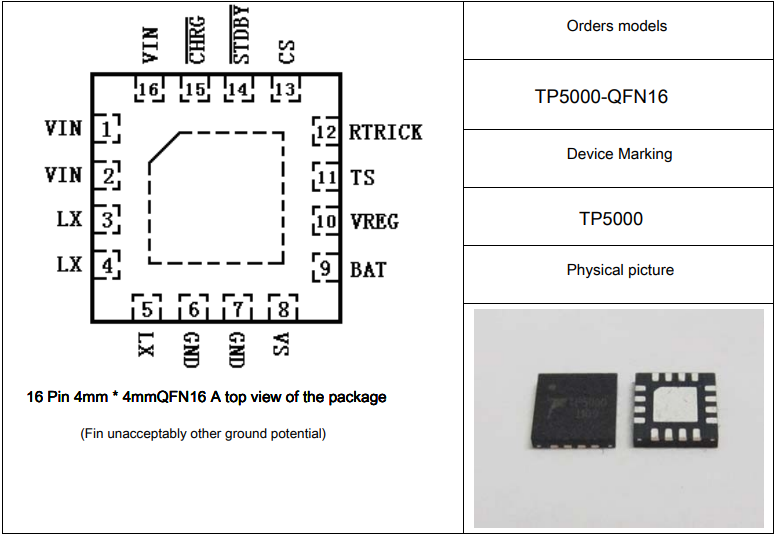
As per the claim TP5000 is a single switch buck-type lithium manganese battery / lithium iron phosphate battery charge management chip. Its ultra-compact QFN16 package Fitted with a simple peripheral circuit, making it ideal for portable devices. TP5000 can handle large current charging management applications. Meanwhile, TP5000 built in input overcurrent, under voltage protection, over temperature protection, short circuit protection, battery temperature monitoring, reverse battery protection.
The TP 5000 IC is a compact charger controller chip designed to charge either one Li-ion or LiFePo4 battery. This module accepts an input voltage range between 4.5V – 9V and its terminating voltage are 4.2V or 3.6V. Here the battery charging current rate can also be modified simply by changing the value of a resistor. The battery charging current rate can also be modified simply by changing the value of a single onboard chip resistor.
Circuit Diagram

BOM
| S.no | Designator | Value | Quantity |
| 1. | IC | TP 5000 | 1 |
| 2 | Resistor | 1KΩ | 1 |
| Resistor | 0Ω | 1 | |
| Resistor | 0.1Ω | 1 | |
| 3 | Capacitor | 10μF | 3 |
| Capacitor | 100nF | 1 | |
| 4 | Inductor | 4.7μH | 1 |
| 5 | Diode | SS34 | 1 |
| 6 | LED | 2 | |
| 7 | Battery | 1 |
Construction and Working
In the above circuit, the TP5000 integrated battery charging IC is based on a switching buck converter, which means it can handle higher currents and not heat up. Here the VIN pin (1,2,16) connects to the input voltage at the positive input terminal between 4.5V to 9V. Next LX pin (3,4,5) is the current output terminal of the external inductor and is connected to a battery charging current of the input terminal. Battery pin 9 connects to the positive battery terminal and VREG (pin 10)acts act as an internal power supply.
TS (pin 11) is used to detect battery temperature at the input terminal. RTRICK (pin 12) is used to set a constant current to provided by an external resistor. CS (pin 13) is a low-end input level will TP5000 in the Lithium-iron phosphate 3.6Voff state voltages. STDBY (pin 14) charge complete output active low. CHRG charge indicator status, both pins 14,15 are connected to the LEDs.
By default, the module is configurated as a Li-ion charger so you should remove the solder jumper F to use it as a LiFeO4 charger. The 0Ω jumper sets the pre-charge / to trickle current to 10% of the battery current, and the 0.1Ω resistor limits the charging current to 1000mA(1A). Adding one more 0.1Ω resistor in parallel with the existing R100 will raise the charging current to 200mA(2A) but then a heatsink must be added to the controller chip. Likewise replacing the 0Ω jumper with a 50KΩ resistor will raise the pre-charge current to 20%.
Breakout Boards
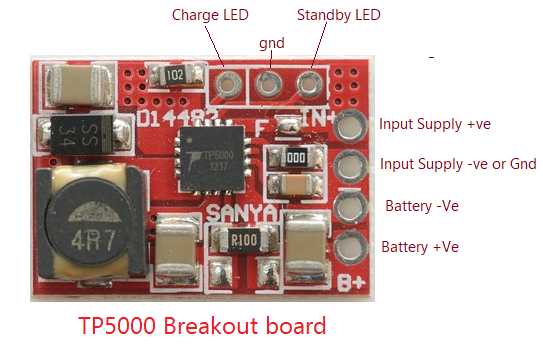
This is a sample of TP5000 Battery charging breakout board, there are many good quality breakout boards available in the market for few bucks.