Last Updated on April 3, 2024
Traffic light is designed with two timer ICs 555 and three LED indicators, this circuit drives three LEDs with different time delay to provide stop, wait, and go signals on road.
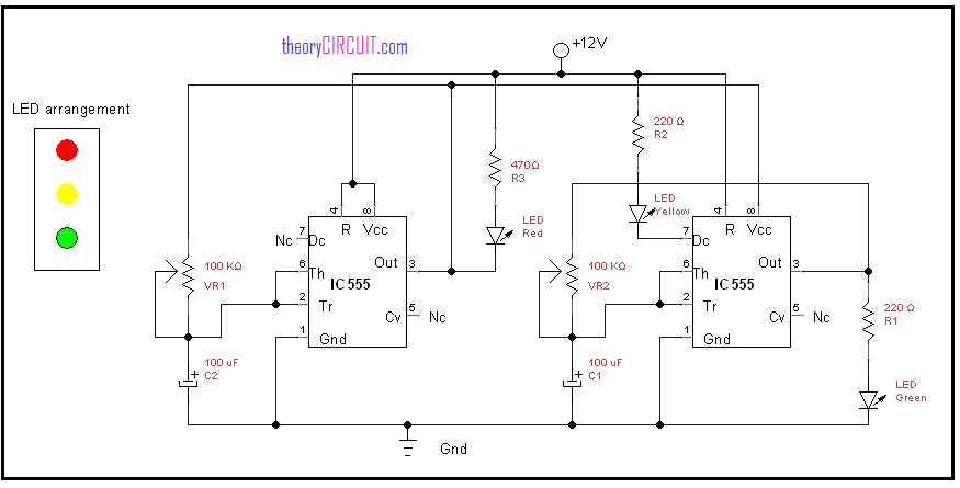
Circuit diagram
If you are looking for Fixed Value Resistor Circuit
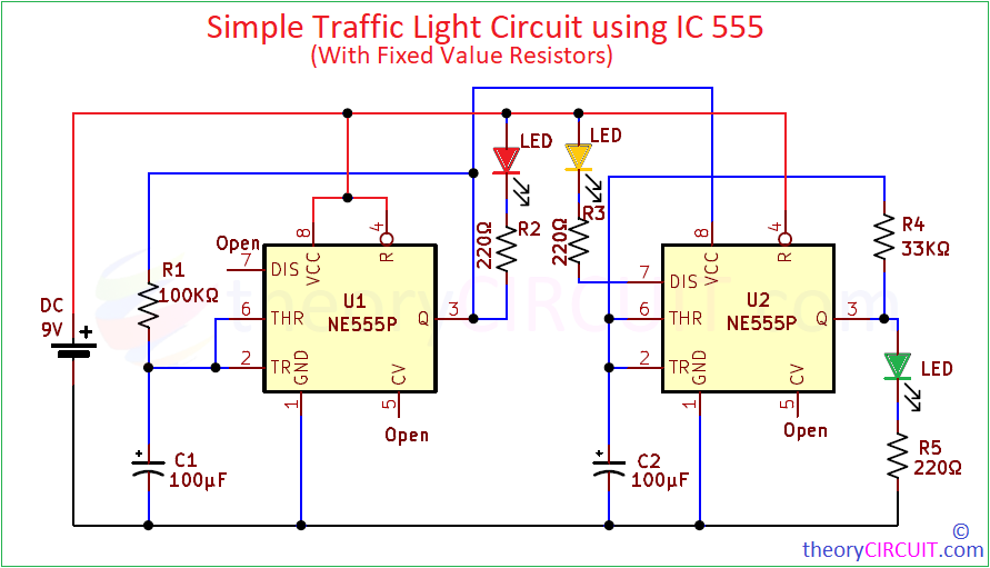
For Construction and Operation Read here… Traffic light circuit using IC 555 with Fixed Value Resistors.
Working Video
Construction and working
Two timer ICs biased with 12 volt power supply, the left side timer provides output through Red LED, the right side timer LED provides output through yellow LED and Green LED, here the yellow LED output controlled by discharge pin, Vcc supply for this IC provides through output and timer elements of left side timer IC 555. By varying VR1 and VR2 variable resistors we can vary the time delay between LEDs, here two timer ICs control voltage pin 5 left as no connection, LED arrangement of traffic light is shown in circuit diagram.
Datasheet
You can get datasheet of IC LM555 here.
I have built this circuit and it works perfectly. A 9VDC battery can run it but the circuit will quickly drain the battery in less than 24 hours.
thanks for your interest 🙂
you can use solar panel and chargeable battery instead.
can you help me with a four way traffic light interface
May be it was caused by the requirement of 12 volt voltage?
Use Reverse Voltage Protection Diode, it may slow down battery drain time.
Can u send me full project report
why not! We can help you to make yourself.
1. Make your project title
2. Write abstract for that title (google you project title)
3. Introduction.
4. Existing system.
5. Problems in Existing system and case analysis
6. Proposed system.
7. Future expansion.
8. Conclusion.
That’s it you made Full project report.
Hope you got it.
Sorry!!!
I mean
Pls I need 4 way traffic light for my Final year project ….please can you help me out with it??
Hello, I have a problem with this circuit in proteus. Red and Yellow red work in the same time . Can help?
Hi Mahmoud El-Kahawy
Make sure about the wiring and black dots in between blue wire represents connection and cross line represents no connection.
The same thing is happening to me on MultiSim. And I made sure the wiring is correct.
Can you pls share the link for the multisim simulation of the traffic light. ?
Proteus Simulation may not give proper output to the passive components.
URGENT!!
hey,
I’m facing some issues , how can i contact you?
I’m using a 9V battery for supply as i have made the circuit on a breadboard.
also, I’m using a 100K potentiometer for variable resistance.
also, could you explain the exact working of the above circuit?
Thanks in advance
Hello , can you please tell me how to set the time delay, I mean what I need to change for varying delay time. And formula for calculating it
I am asking for the project in electrical and electronics based on traffic lights with improvements
Can I also ask for the full project report?
How would you compute the time on and time off for each led?
please i need steps at which u used to build or connect the components
can u tell me which type of 4017 ic use for traffic lights mean type voltage
Please can you send me ckt diagram in multisim because I do not done this project using this diagram so please send me to this diagram using multisim .
My son (11th grade) is trying to build a similar circuit for a STEM competition. I have a background in circuits but it’s been years. The idea is that the light changes based on “seeing” a car. He’s thinking of an RFID sensor. Can we use this same circuit and add the sensor to “start” the process? Any insight into what this new circuit might look like? Thanks for your help!
I couldn’t blink Yellow led
May i know y!? Need a help!
I have tried this circuit and cannot get it to work (have checked the wiring). when I disconnect connection from left hand IC pin 3 to right hand IC pin 8 red LED operates as it should. With the same wire disconnected I connect right hand IC pin 8 to +V and green and yellow LED’s work as they should. However when I connect everything back to drawing Green LED is on and stays on. Any advice?
Built the circuit and green LED lights and stays on. Triple checked wiring ( all ok). Disconnected wire connecting left IC pin 3 to right IC pin 8. Red LED flashed as expected. Then with that wire still disconnected applied power to right IC pin 8 and green and yellow LED’s flashed as expected. Any thoughts?
can anyone help me? i made this circuit in multisim but there was an error red and yellow light blink very fast and also how to use and where is variable resistor in multisim
Did you end up figuring out the solution because I’m facing the same problem right now?
In my case the red and the yellow light is blinking simultaneously . May I know what is wrong with it.
I have checked the wirings multiple times .
What is the voltage of the 100uF capacitors?
All 3 leds light stays on at the same time, no blinking alternatively.
What is the seventh pin not used in the first 555timer ic?