Last Updated on March 16, 2024
The simple and reliable Vibration Alarm Circuit using Timer IC 555 designed to produce buzzer sound, and this circuit constructed by using Vibration sensor switch SW – 18020P and timer IC555 and few easily available components. The SW – 18020P sensor has two terminals and there is no contact between terminals in idle condition. When Vibration or External force applied on sensor two contact pins of sensor are closed. This sensor is suitable for producing trigger signal to the timer ICs and as well as for microcontrollers.
The SW 18015P/20P series sensors are spring type and No directional Vibration sensor trigger switch that means it can detect virbration from any angle. This sensor is in open circuit (OFF State) when it is static condition. Comes to ON state when vibration or movement occurs. This is achieved by centrifugal force inside the spring setup.
SW 18020P Vibration Sensor
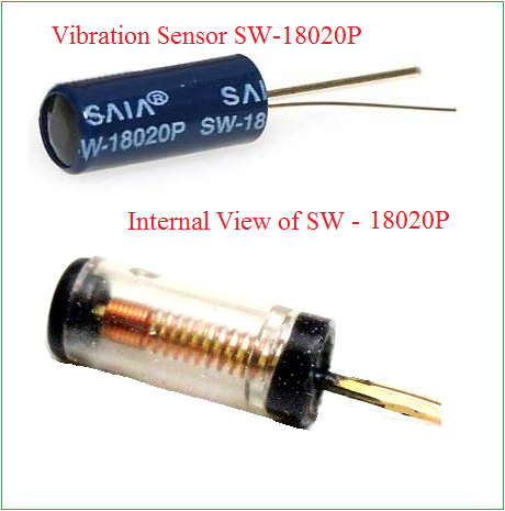
You can see the physical view of vibration sensor SW – 18020P and internal view. This sensor works in maximum voltage range of 12V and maximum current value < 5mA. It creates < 10MΩ during idle condition (no vibration detected) and produce < 5Ω during vibration detection. It has fast response time as 2ms, and has ambient temperature range < 100°C. It is suitable for different applications that needs vibration detection.
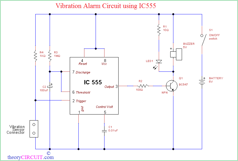
Circuit diagram for Vibration alarm
Construction and Working
This circuit has timer IC 555 configured in monostable mode. It produce buzzer sound and light indication upto two minuets during the vibration detection. You can change this alarm sound duration by changing the timer elements R3 and C2.
T = 1.1 * R * C
for given circuit
Tmono = 1.1 * R3 * C2
= 1.1 * 1MΩ * 100µF
= 1.1 * 1000000 * 0.0001
Tmono = 110 Seconds.
Try our New IC 555 Timer Monostable Multivibrator Calculator for timing calculations.
When the vibration detected by the sensor, it will produce trigger signal and it triggers the timer IC 555 hence it produce Mono timing pulse up to 110 Sec. The output pulse taken from pin 3 is applied to the NPN transistor BC547, here the Q1 reacts as switching device and makes contact between buzzer, LED to ground supply it lasts up to mono pulse end. So the buzzer produce alarm sound. If the circuit deserves fixed place means you can connect +5V DC adapter to the alarm circuit.
IC 555 Pinout and Internal Blocks
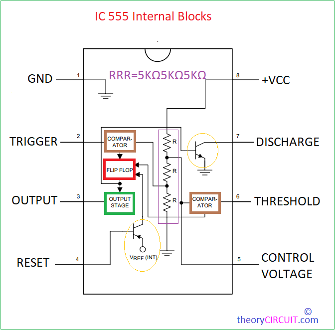
The Timer IC 555 is a all rounder electronic element that used in different types of circuits and applications. This tiny IC can generate precise time delays by using external timing Element so this IC used in countless timing circuits and applications. This IC internally have resistors, capacitors, comparators, and flip-flops for its operations. Hence it uses only few external components for its full operation. It is operates in Monostable, Astable and Bi-stable modes. Due to low power consumption this IC preferred to use in Battery powered applications
good day
how is the sensitivity of this circuit adjusted? say if i wanted it more sensitive, what would changes would have to be made to the circuitry?
And or making it less sensitive. How can this be achieved?
Thank you