
Last Updated on April 11, 2024
World is moving towards Wireless Energy transfer methods, several types of wireless energy methods are being tested and prototypes are made out of it. Now a days wireless Mobile charging gets its own track, This article may help you to design your own wireless gadgets / mobile charging device.
How Wireless Energy Transfer Works?
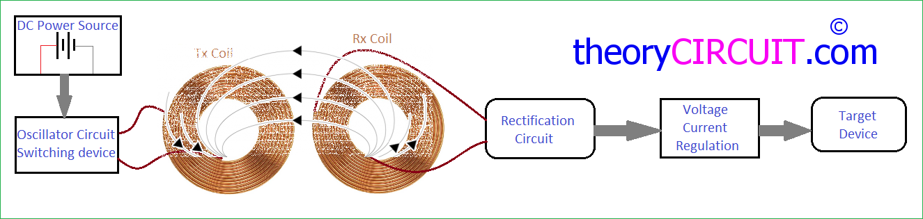
Inductive Coupling method helps us to transfer Energy in shape of Magnetic flux but it is possible for few inches only, it may increase in near future.
The DC power source is provides bias to the Oscillator circuit and Switching device, this circuit converts DC supply into high frequency switching pulse, when these pulse reaches the Tx-Coil then it converted as a Magnetic flux. Rx-Coil is placed near to the Tx-Coil, so that produced magnetic flux Induces the Rx-Coil hence an alternate energy produced by Rx-coil. Rectification circuit makes Direct current output from the Rx-coil energy. Voltage/Current regulation circuit limits energy and applies to the target device.
Wireless Gadgets Charger Circuit
Transmitter Circuit
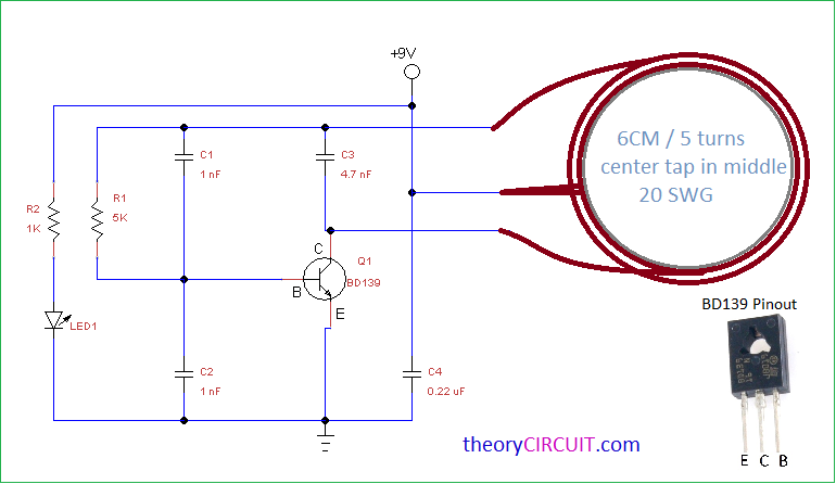
Construction and Working
This circuit constructed to produce high frequency magnetic flux. The center tapped Coil is made through 20 SWG Enameled copper wire 6 CM dia and 5 turns with center tap in middle. The BD139 NPN transistor reacts as a Switching device and oscillates high frequency signal with the help of R1, C1 and C2 Resonator elements.Here LED 1 indicates the presence of bias to this circuit.
Receiver Circuit
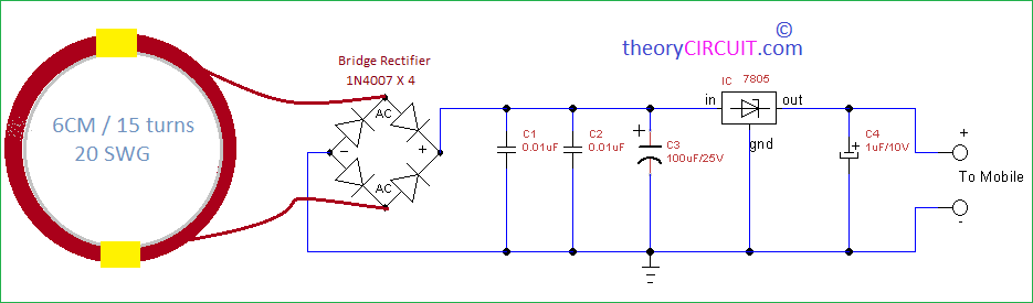
Construction and Working
It starts with 20 SWG enameled copper wire 6 CM dia 15 turns coil and connected to the bridge rectifier (1N4007 X 4) then filter capacitors C1, C2, C3 connected across the output terminals of bridge Rectifier, IC 7805 positive voltage regulator provides regulation to DC supply from rectifier and output supply is ready for to charge your gadgets / mobile battery.
Prototype Note:-
Make sure about Gadgets / Mobile battery specifications and output characteristics V / I of this circuit are suits well.
This circuit is made for experiment and not suitable for on field applications.
Which type of oscillator is used in transmitter??
how much current and gotten in the load?
Hi the center tap midle means 10 turns 5 before mid and 5 after or just 5 and have midle tap some where in 2 or 3th turn ??
What could I use for the plate to solder all of this onto
The transistor makes as the oscillations
by rapidly switching on and off
what’s the RC resonance frequency in this example?
Hello . How many amperes should the power supply of the transmitter circuit be??
Hi meysam
In Wireless Gadget charger circuit we used BD139 NPN transistor as per the datasheet claim it can handle 1.5A current, but we recommend you to use below 1.5 amperes.