Last Updated on March 16, 2024
In Some Case, To control Some Electronic or Electric Load we need Single switch like Push button and we start or stop the function of load with one single Push. To Construct Push ON Push OFF Circuit we don’t need to depend on Microcontrollers or timer ICs, we can built Simple Single Push Button ON OFF Relay Circuit by using few transistors and a Capacitor.
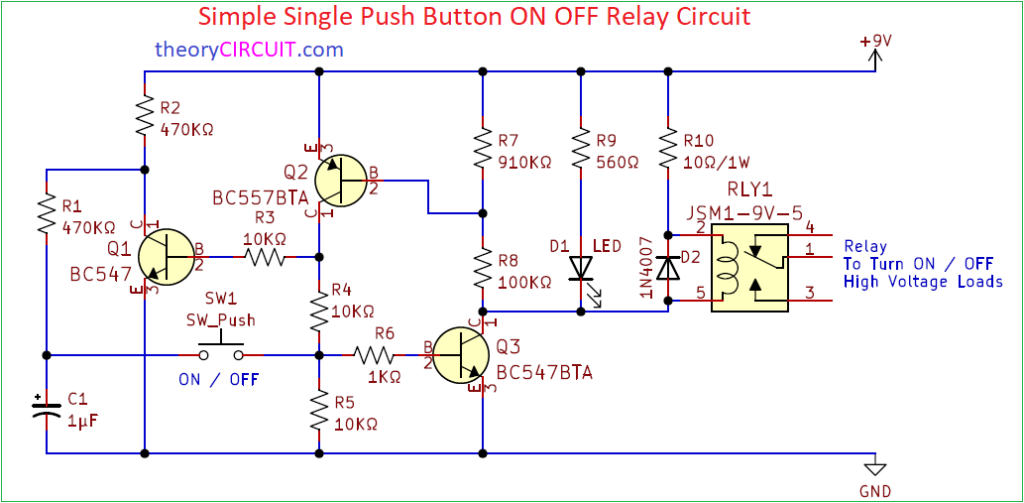
Here Push button ON OFF circuit Constructed to turn ON OFF Electric load connected with the Relay. We can construct this circuit in common PCB. All components used in this circuit are through hole components.
Circuit Diagram
Components Required (BOM)
| S.No | References | Value | Quantity | ||
| 1 | Q1,Q3 | Transistor BC547BTA – TO92 package – NPN | 2 | ||
| 2 | Q2 | Transistor BC557BTA – TO92 package – PNP | 1 | ||
| 3 | RLY1 | Relay JSM1-9V-5 | 1 | ||
| 4 | R1, R2 | Resistor 470KΩ | 2 | ||
| 5 | R3, R4, R5 | Resistor 10KΩ | 3 | ||
| 6 | R6 | Resistor 1KΩ | 1 | ||
| 7 | R7 | Resistor 910KΩ | 1 | ||
| 8 | R8 | Resistor 100KΩ | 1 | ||
| 9 | R9 | Resistor 560Ω | 1 | ||
| 10 | R10 | Resistor 10Ω/1W | 1 | ||
| 11 | C1 | Capacitor 1µF/50V | 1 | ||
| 12 | SW1 | Tactile Push Button Switch | 1 | ||
| 13 | D1 | LED Green 5mm | 1 | ||
| 14 | D2 | Diode 1N4007 | 1 |
Construction & Working
This Circuit Operates in 9V DC power supply hence we used 9V Relay, and you can choose Relay depends on the operating voltage you applied to this circuit (It can operate with 3V to 12V DC). Capacitor C1 holds the voltage flowed through Resistor R1 and transistor Q1 connected between R1, C1 elements, to discharge voltage when push button pressed. When Push Button pressed the voltage stored in C1 flows to the Q3 transistor base through R6 and turn ON Q3. LED and Relay Connected to the collector terminal of Q3 gets Ground supply and gets turn ON.
When push button pressed during ON condition Q2 transistor allows positive voltage to the LED and Relay through R8 and makes the LED and Relay turn OFF. This operation repeats whenever the push button switch pressed.
This Circuit can be easily constructed on common PCB board or dot board.

there are many complains that this is wrong design please reconsider the fault
Hole-mount over service mount? Interesting. Any particular reason why it opted for this choice in terms of design?