
Last Updated on March 16, 2024
Simple Voltage Level Readout Circuit designed by using ICLM339 from Texas Instruments. This circuit contain Quad differential comparator from IC LM339. This circuit operates with 12VDC supply. This circuit given here uses a comparator circuit to compare the input values to check whether the input is above or below the reference value.
For example, the reference point of a voltage level circuit are 3V,6V,9V,12V and the corresponding LEDs are LED1,LED2,LED3,LED4, respectively. If we apply an input voltage of 7V then the LED1 and LED2 becomes ON and the LED3 and LED4 remain OFF. because the input values is above the reference point 3V and 6V but below 9V and 12V.
Now, the comparator will be in a high state or positive saturation when the input voltage or positive saturation when the input voltage at the Non-inverting terminal is larger than the voltage at the inverting terminal.
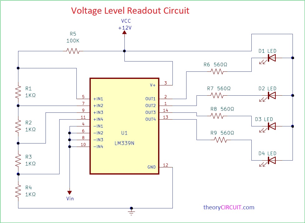
Circuit Diagram
BOM
| S.NO | Designator | Value | Quantity |
| 1 | R1,R2,R3,R4 | 1KΩ | 4 |
| R5 | 100KΩ | 1 | |
| R6,R7,R8,R9 | 560Ω | 4 | |
| 2 | IC LM339 | 1 | |
| 3 | LED | 4 (desired color 5mm) |
Construction and Working
Here the reference voltages are applied by using voltage divider network of equal resistor(1K). then the all Non-inverting terminal of the comparator are connected the voltage divider and supply. Here, we have four 1kΩ resistor and if the voltage across total resistor is 12V then the voltage across each resistor is 12/4=3V.
In this circuit all the Inverting terminal of four comparator connected to the input signal . If the input signal a value above reference point then the output of the comparator act as a sink and the LED light ON. The output only provides a path to the ground pin not to the voltages source. hence we have to connect the load across the positive terminal of the supply and the output pin of the comparator. So, here in the circuit al the cathode of LEDs is connected to the output and the anode to the Vcc. Hence we have connected the reference value to the Non-inverting terminal of the comparator and the input signal to the Inverting terminal.
If the input voltage is of a smaller range then you can adjust the reference voltage levels by adding a series resistance with resistor R1 to R4. The voltage across the total resistor R1 to R4 will be Vt=Vcc-VR5. This Circuit can be easily constructed on common PCB board or dot board.