
Last Updated on March 29, 2024
Cost Effective Method of obtaining Regulated DC supply is using Zener Diode as a Voltage Regulator device. In this Article 1.5v Regulated DC Power Supply Circuit using Zener Diode designed and tested along with Bridge Rectifier. In this circuit 1.5V Zener Diode used to Regulate and give 1.5V from unregulated 6V DC supply through bridge Rectifier.
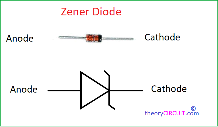
What is Zener Diode?
As we know A Zener Diode or Breakdown diode is a PN diode Specially designed to operate in the breakdown region in Reverse bias condition. Depends on the PN junction doping level this Zener Diode Conducts in Reverse bias when a Certain Specified voltage is reached. This operation called as Zener breakdown.
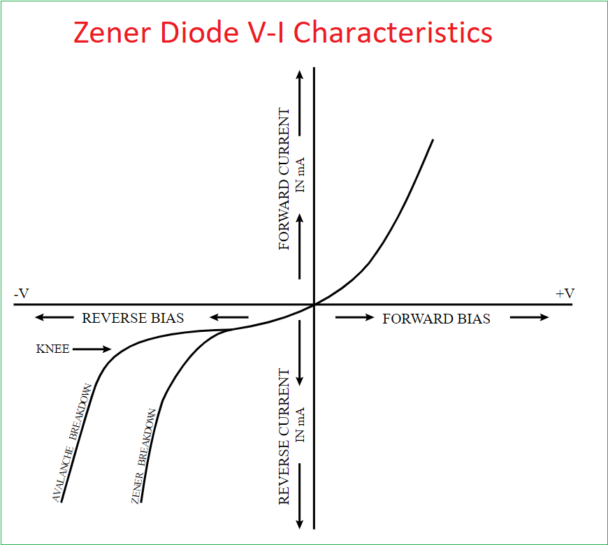
Zener Diode V-I Characteristics
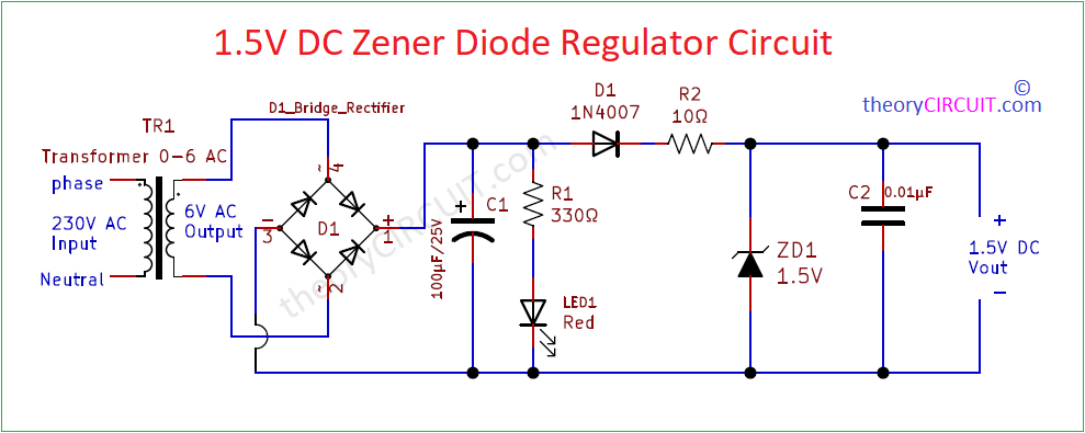
Circuit Diagram
Components Required (BOM)
| S.No | Designator | Value | Part Number | Quantity |
| 1 | TR1 | 230V to 0-6V AC | 0-6V Stepdown Transformer | 1 |
| 2 | C1 C2 | 100µF/25V 0.01µF | Electrolytic Disc capacitor | 1 1 |
| 3 | R1 R2 | 330Ω/0.5W 10Ω/0.5W | – – | 1 1 |
| 4 | D1 | – | Bridge Rectifier Module | 1 |
| 5 | LED1 | Red | – | 1 |
| 6 | ZD1 | 1.5V | Zener Diode | 1 |
| 7 | D | 1N4007 | Diode | 1 |
Construction & Working
This Circuit Gives Constant Regulated 1.5V DC supply from unregulated DC. This is a standalone power supply circuit hence direct 230V mains supply is reduced to 6V AC by using stepdown transformer, then bridge Rectifier module (or Four 1N4007 Diode in bridge form) Converts 6V AC into 6V DC supply then this DC supply Filtered by Capacitor C1, then LED1 indicates the presence of input DC to the Zener Regulator circuit, Here diode 1N4007 is used as Reverse supply protection device.
1.5V Zener Diode connected parallel and in Reverse bias to the unregulated DC supply. When the Input DC Supply to this Zener diode reaches 1.5V then Zener breakdown occurs and allows only 1.5V at the output end. Capacitor C2 acts as High frequency ripple filter.
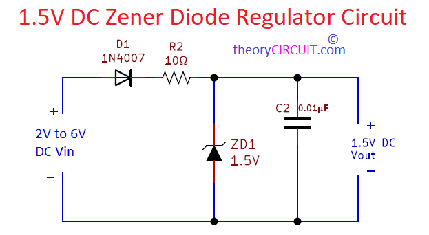
If you are using Zener diode in a DC supply Circuit then you can directly connect Zener diode in Reverse bias to obtain Desired Regulated DC supply. Before implementing Zener diode in a Circuit we have to see the Maximum Input and Output Voltage along with current Specifications.