
Last Updated on March 16, 2024
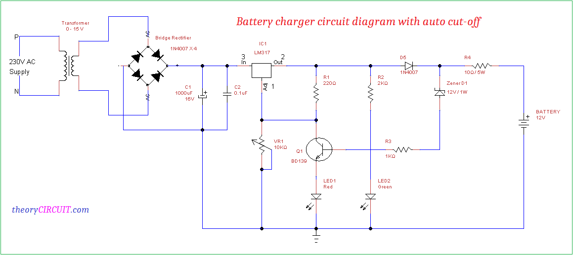
Here Battery charger circuit diagram designed by implementing adjustable voltage regulator LM317 with auto cut off feature. This circuit will give adjustable DC supply output and charges battery ranges from 6 volt to 12 Volt.
The LM317 is a monolithic Integrated IC comes with three different packages and it is a positive adjustable voltage regulator delivers 1.5A of load current, output voltage can be adjusted from 1.2 to 37 V.
Circuit diagram
Construction and Working
Step down (230V to 15V) transformer is used to step down the AC power supply and bridge rectifier (1N4007 X 4) converts AC supply into DC supply, C1 and C2 capacitor performs filter operation then IC1 LM317 regulates the DC power supply, VR1 variable resistor changes the supply to Adjust pin of voltage regulator and it changes the output voltage range.
Here Green LED represents the Charging condition and Red LED indicates the fully charged battery when the battery becomes fully charged then reverse voltage through Zener diode (12V) flows to transistor BD139 base and makes it turn ON due to the conduction in transistor Adjust pin of Voltage regulator connected to ground and cut the output voltage from regulator.
Connect heat sink with voltage regulator LM317 to avoid thermal runaway.
LM317 Vo Calculation
LM317 regulator gives variable output voltage and it can be varied by using Adjust pin, We can calculate Vo from IC LM317 as,
VO = VREF (1 + R2/R1) + IADJ R2
It can be modified depends on this circuit design as,
VO = VREF (1 + VR1 / R1) + I ADJ VR1
Here VO represents output voltage from regulator IC.
Hi my circuit chargers with 60mA but so far the charger has not disconnected and the voltage over the battery is 13.66V can someone please contact me for help
Use 11v zener or try to increase 1k resistor.
I mean use 11v zener or try to reduce 1k resistor to get Iz minimum to turn on transistor
Hi Adrian. When the battery charge reaches 13.66 or 13.7 volts, rotate the resistor with a screwdriver slowly until the green light turns on. From now on, the current is disconnected when the battery is charged.
Input 12v 2amp DC , battery 12v 7ah , need to connect WiFi modem for uninterrupted supply , I request you to please let me know necessary modifications .
Thanks
Sachin Patil
how can the battery get more than 12V for charging when the zener diode of 12V is used here ?
kindly also specify the function of R4, why should I consume some of charging current in that resistor?
There is a RED LED also in circuit typically give around 1.8 voltage drop plus 12 volt of zener which ultimately give 13.8 voltage at the output for charging the 12 Volt battery. over which the circuit stops charging.
but then there is base to emitter drop as well as some drop across base resistor, R3….
and still want to know why to use R4? why should I waste charging current?
Can I connect 2A transformer?
Hi, may I know what is the usage of R4?
I guess R4 is there to limit the charging current.
Thanks for the extra info on thos circuit. I noticed you used a 12v zener diode as you say there is a 1v odd drop over the led. Is there not a voltage drop across the 1k gate resistor as well? I also saw another website saying that R4 should be 100ohm and another saying it should be 2.2ohm otherwise theres a 5v drop over R4 but why even have R4?
How can the transistor not instantly switch on? cause isn’t the voltage regulator outputting a voltage higher than 12V? I read somewhere that when you’re charging a battery the voltage should be higher than than the battery voltage. So for 12V the voltage regulator should be outputting more than 12V+?
pls send me a circuit diagram for Li
ion battery
that voltage is correct for the standby battery its range is from 13.6 to 13.8
usually 13.5 to 13.8 with room temperature. higher temperature it could be less and lower temperature more
Hi,
1.Increase the value of R3 to 33K.
2.Connect led 1 series to the collector of Q1 and connect Q1emitter to GND.
3.Reduce the value of R1 to 180 ohms.
4.Connect a 1.8k resistor series to VR1 and reduce the value of VR1 to 4.7 or 5k.
5. Change the value of R4 to 22 0hms 3 or 5 watt.
6. Now with out connecting the battery adj VRIto get 14.1v after 22 ohm resistor also note the base voltage of Q1 it should he around 0.558 t0 0.600v now connect the battery and check it will charge your bat up to 13.85 or 13.9v. Goodluck Sambath kumar.
Can you kindly explain why R4 is used and you say to change its value upto 22 ohms!!! If charging current is 500mA, this R4 will drop 11V!!! Kindly correct me if I am getting it wrong…
Hi,
Forgot to tell you one thing the collector of Q1 to be connected only to the top end of VR1 and not to the pin no 1 of LM317. Sambathkumar.
Sir iwant to know the resistor how many whatts for all cause i want to try this project
hi there,
Fed up of reading of non working circuit. Is there any really working circuit ???
welldone sir, please can i get the design calculation for the auto cut-off arrangement
My battery charger is drawing current initially 3 amp and then gradually coming down up to 2.4 amp after approx. 10 hrs. And then it is getting autocut but still is showing 0.8 -1.0 amp. current on ammeter. What does it mean? Is my charge (bought online) is faulty? How can I rectify it?
Hi
can i use this circuit to charge a 4v lead acid battery.
what changes do i need to make to charge a 4v battery ?
regards
Joe
Good evening sir. I’m just a novice when it comes to electronics. Please how can the circuit be modified to charge a 24v lead- acid battery for inverter? Thank you. I like the circuit. It’s simple to make.