
Last Updated on December 2, 2017
Oscilloscope is a electronic test device to measure signals in two dimensional graph. Oscilloscope may called as CRO (Cathode Ray Oscilloscope), Scope or DSO (Digital Storage Oscilloscope). Here in this article we are going to learn few basic measurement and operating technique on standard oscilloscope.
Different oscilloscopes are made by more number of company but the basic measuring terms remains same they are voltage measurement, frequency or time measurements. Many oscilloscope comes with two channel operation here we have taken two channel CRO as example.
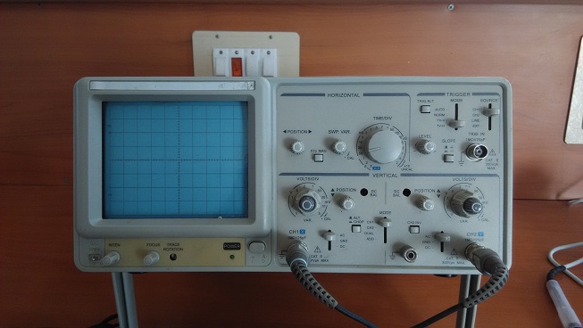
For an normal oscilloscope there will be three basic section presents they are
- Vertical section
- Horizontal section
- Trigger section.
Vertical section
This section helps to vary the signal level in vertical scale and this measures voltage range with volt/div control.
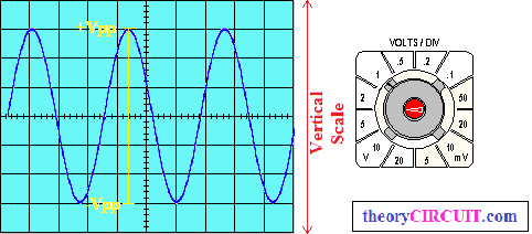
Two channels has individual Volts/Div control hence we can vary the two channel signal individually and measure the voltage range. Here an example for vertical section measurement is illustrated,
[stextbox id=”grey”]
+Vpp to -Vpp (Positive peak to Negative peak) of signal X Volts/Div
6 X 2 = 12 Volts
[/stextbox]
Horizontal section
The horizontal section is also called as Time/Div section which is common for all channels, this will measures the time and frequency of signals.
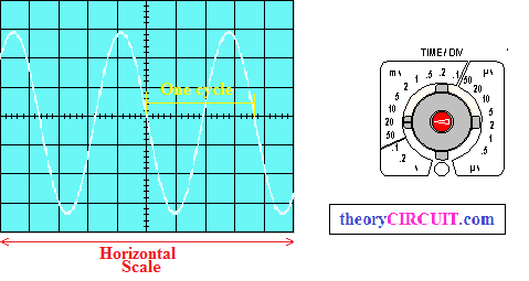
Here an sine signal measurement is given for example, measurement of time or frequency done as
[stextbox id=”grey”]
Number of Sections covered by one cycle X Time/Div
3.6 X 20 ms = 72 ms (Time)
Frequency = 1/T = 1/72 ms = 13.8 Hz (Frequency)
[/stextbox]
Formula for frequency / time calculation and conversion http://www.sengpielaudio.com/calculator-period.htm
Trigger section
This section helps to hold the oscillating signal or moving signal depends on time, by varying trigger alt or trigger level and source mode selection we can hold running signal.
The Oscilloscope Probes
If you use not proper or damaged probe means you cannot get perfect measurement in oscilloscope hence we need good probes.
Different types of Oscilloscope Probes

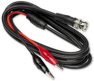
First one is BNC probe and second one is crocodile probe
Before taking the probes into measurement check the function of probes by known signal source.
Using an Oscilloscope
Step 1: Turn ON the oscilloscope and wait till warm up and straight line appearance in screen (adjust x – y positions level if not dot or straight line appeared for long duration)
Step 2: Choose the channel to be used for measurement and connect the probe.
Step 3: Set proper focus and magnification level.
Step 4: Connect the probe ground pin in testing circuit ground and connect probe positive pin at test point of circuit (Measurement point of circuit).
Step 5: Make adjustment in Volt/Div, Time/Div and trigger section till the signal appear as good to measure.
This article gives basic idea to operate common oscilloscope, If you need to know more about oscilloscope then take a look at user’s manual of your oscilloscope !