Last Updated on March 16, 2024
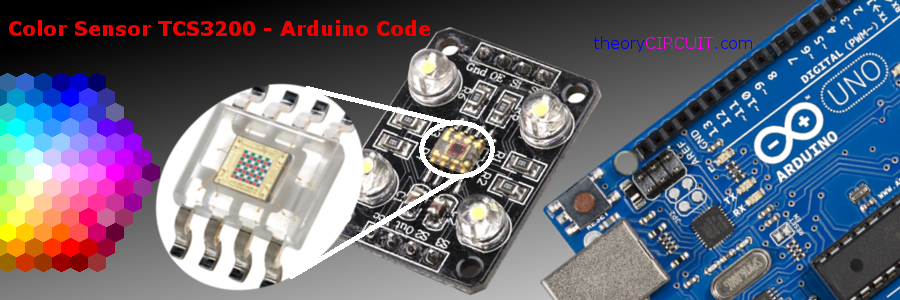
This article about Color Sensor TCS3200 Arduino interfacing will give you in & out details about color sensing and Sensing true color brings lot of possibilities and applications, when I searching for perfect Color Sensor to detect different range of color, i found TCS3200 programmable color light to frequency converter from Texas Advanced Opto electronic Solutions (TAOS).
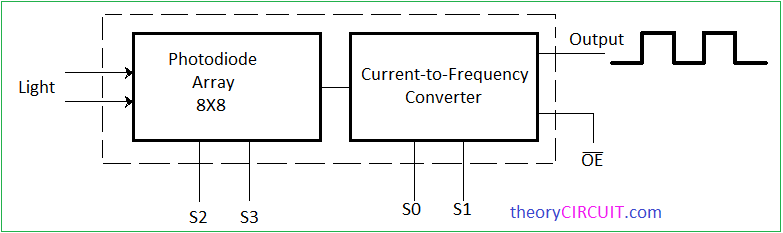
The TCS3200 and TCS3210 programmable color light-to-frequency converters that combine configurable silicon photodiodes and a current-to-frequency converter on a single monolithic CMOS integrated circuit. The output is a square wave (50% duty cycle) with frequency directly proportional to light intensity (irradiance). The full-scale output frequency can be scaled by one of three preset values via two control input pins. Digital inputs and digital output allow direct interface to a microcontroller or other logic circuitry. Output enable (OE) places the output in the high-impedance state for multiple-unit sharing of a microcontroller input line.
In the TCS3200, the light-to-frequency converter reads an 8 x 8 array of photodiodes. Sixteen photodiodes have
blue filters, 16 photodiodes have green filters, 16 photodiodes have red filters, and 16 photodiodes are clear
with no filters. In the TCS3210, the light-to-frequency converter reads a 4 x 6 array of photodiodes. Six photodiodes have blue filters, 6 photodiodes have green filters, 6 photodiodes have red filters, and 6 photodiodes are clear with no filters.
The four types (colors) of photodiodes are interdigitated to minimize the effect of non-uniformity of incident irradiance. All photodiodes of the same color are connected in parallel.Pins S2 and S3 are used to select which group of photodiodes (red, green, blue, clear) are active. Photodiodes are 110 μm x 110 μm in size and are on 134-μm centers (from datasheet).
TCS3200 Sensor Pinout
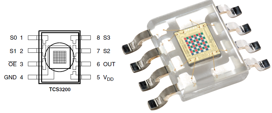
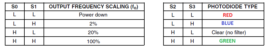
The pins S0 and S1 are Output frequency scaling selection inputs, pin number 3 is Output Enable pin and also it is a active low pin normally connected with ground supply it Enable for fo. The power supply requirement for this sensor is from 2.5V to 5.5V and it is applied through pin 4 (gnd), and pin 5 (Vdd). The Output frequency (fo) taken from pin 6, S2 and S3 are responsible for Photodiode type selection inputs.
TCS 3200 color Sensor Module Circuit diagram
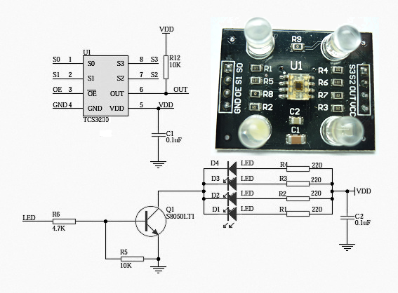
This Sensor contains photodiode array hence it needs light source to detect colors, so that four white LEDs are connected around the sensor. The circuit diagram represents typical tcs3200 module, it can be modified depends on requirements.
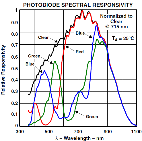
This response curve represents wavelength of color in horizontal axis and Relative responsivity in vertical axis.
Output-frequency scaling is controlled by two logic inputs, S0 and S1. The internal light-to-frequency converter generates a fixed-pulsewidth pulse train. Scaling is accomplished by internally connecting the pulse-train output of the converter to a series of frequency dividers.
Divided outputs are 50%-duty cycle square waves with relative frequency values of 100%, 20%, and 2%. Because division of the output frequency is accomplished by counting pulses of the principal internal frequency, the final output period represents an average of the multiple periods of the principle frequency.
The output-scaling counter registers are cleared upon the next pulse of the principal frequency after any transition of the S0, S1, S2, S3, and OE lines. The output goes high upon the next subsequent pulse of the principal frequency, beginning a new valid period. This minimizes the time delay between a change on the input lines and the resulting new output period. The response time to an input programming change or to an irradiance step change is one period of new frequency plus 1 μs. The scaled output changes both the full-scale frequency and the dark frequency by the selected scale factor.
The frequency-scaling function allows the output range to be optimized for a variety of measurement techniques. The scaled-down outputs may be used where only a slower frequency counter is available, such as low-cost microcontroller, or where period measurement techniques are used (from datasheet).
Color Sensor TCS3200 Arduino Hookup
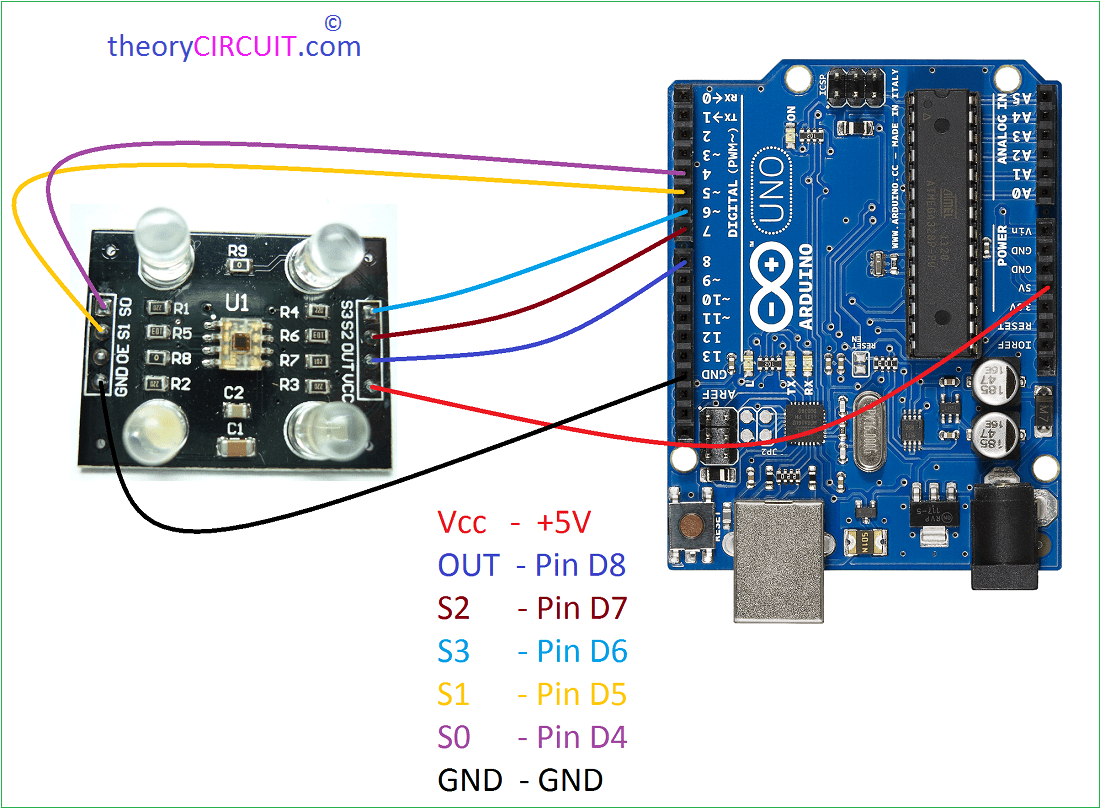
This TCS3200 sensor module can be easily interfaced with Arduino development board, Connect the OUT pin of sensor to Arduino digital pin D8 and connect S2,S3 to Pin D7,D6 by the way connect S1,S0 to Pin D5,D4 finally connect bias to the sensor Vcc to 5V and Gnd to Gnd pins, thats all after that upload the following Arduino code for color sensor TCS3200.
Arduino Code
#define S0 4
#define S1 5
#define S2 6
#define S3 7
#define sensorOut 8
int frequency = 0;
void setup() {
  pinMode(S0, OUTPUT);
  pinMode(S1, OUTPUT);
  pinMode(S2, OUTPUT);
  pinMode(S3, OUTPUT);
  pinMode(sensorOut, INPUT);


  digitalWrite(S0,HIGH);
  digitalWrite(S1,LOW);

  Serial.begin(9600);
}
void loop() {

  digitalWrite(S2,LOW);
  digitalWrite(S3,LOW);

  frequency = pulseIn(sensorOut, LOW);

  Serial.print("R= ");
  Serial.print(frequency);
  Serial.print("  ");
  delay(100);

  digitalWrite(S2,HIGH);
  digitalWrite(S3,HIGH);

  frequency = pulseIn(sensorOut, LOW);

  Serial.print("G= ");
  Serial.print(frequency);
  Serial.print("  ");
  delay(100);

  digitalWrite(S2,LOW);
  digitalWrite(S3,HIGH);

  frequency = pulseIn(sensorOut, LOW);

  Serial.print("B= ");
  Serial.print(frequency);
  Serial.println("  ");
  delay(100);
}
Reference
tcs3200 color sensor Datasheet