
Last Updated on March 16, 2024
A Electromechanical switch is called as Relay. It reacts as Automatic switch to control (just ON/OFF) large voltage load by using low voltage signal. We use DC (Direct Current) supply to Energize electromagnetic coil placed in relay so, it is referred as DC relay switch.
You know what happen when AC supply given to the coil, there will be varying magnetic field not suitable for constant switch (ON/OFF) operation that’s why here DC used.
Relay Construction
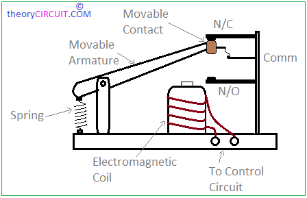
The Relay has Electromagnetic Coil turned around a metal piece this will reacts as magnet when coil gets energized. Movable Armature attached with spring exactly placed above the electromagnet setup and makes contact between common terminal and Normally closed contact (N/C), with out any supply or zero input supply, this condition may be termed as normally open relay. When the coil get energized movable armature attracted by electromagnet and N/O contact becomes closed and N/C becomes open.
Types of Power Relay Switch
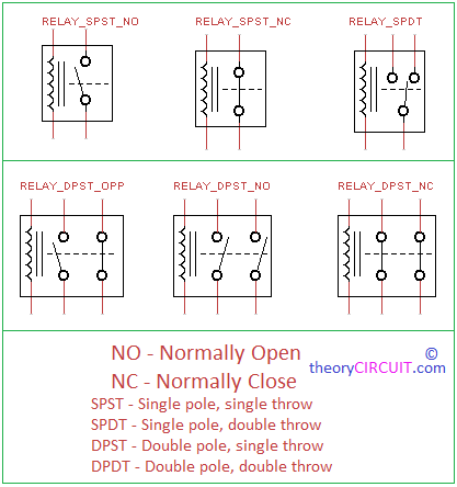
Relay can be found in different forms, depends on the switch contacts, poles and throws. Single pole single throw (SPST) a single switch and the contact is normally open or normally close. Single pole Double throw (SPDT) is a most common relay used for electronics projects and it has N/O and N/C contacts. Double pole type relays are has two contacts either close or open same together.
Relay Operation
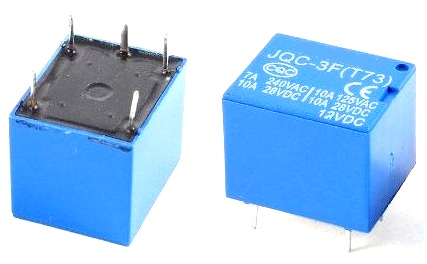
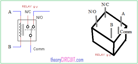
The Relay can be found in this physical appearance. There is five contacts, two contact for electromagnetic coil and N/C, Common, N/O terminals.
Relay Pinout
How to use Relay in Circuit?
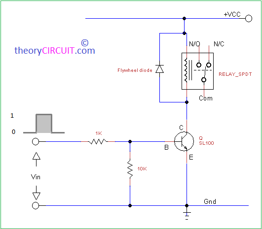
Typical application circuit given for DC Relay switch. The magnetic coil is connected between bias through switching transistor. To protect the coil from back emf flywheel diode placed in reverse bias across the coil. The input Vin to the switching transistor base makes conduction through transistor hence the coil connected to bias directly. It makes coil energized, when Vin downs transistor comes to cutoff and disconnects relay coil from bias.
Solid state Relay
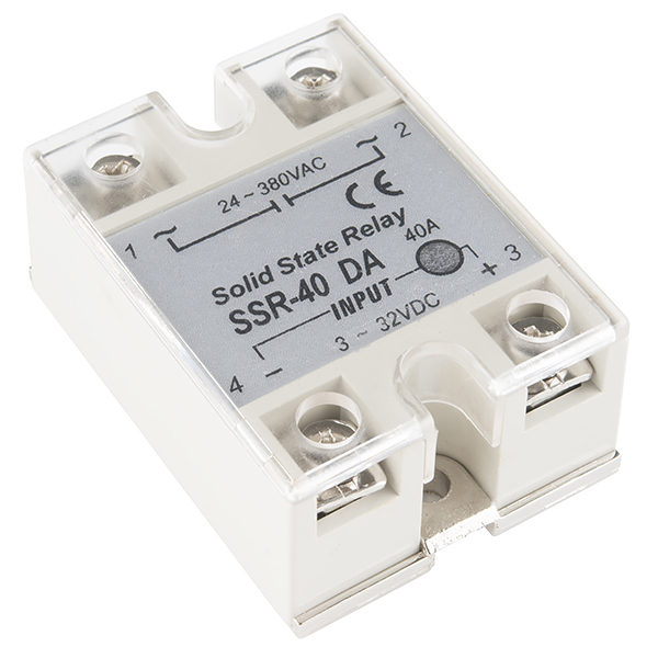
Some critical appliance needs constant surge and spike free power supply. When we employ electromechanical switch it creates surge and spark during switch state changing, to avoid this situation solid state Relays are used.
Solid state Relay Circuit diagram
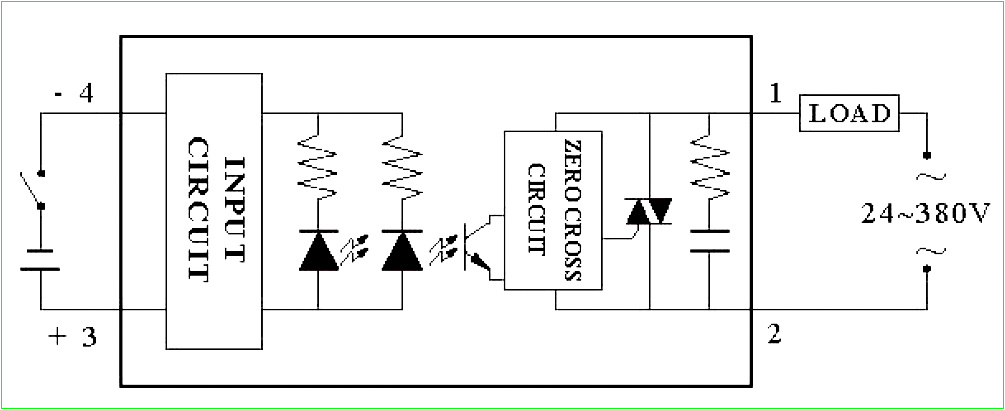
It utilize light signal and there is no moving parts. Input to the solid state relay converted as light signal and photo transistor receives light and makes current flow variation, the zero cross level detector circuit detects the pulse and turn on the thyristor this action makes close contact to the load and power supply. It takes input from 3 V – 32 VDC and controls output from 24 – 380 VAC.
This is very innovative and informative also useful Article. Thank you for sharing this Article.Thanks
Thanks for your Appreciation 🙂