
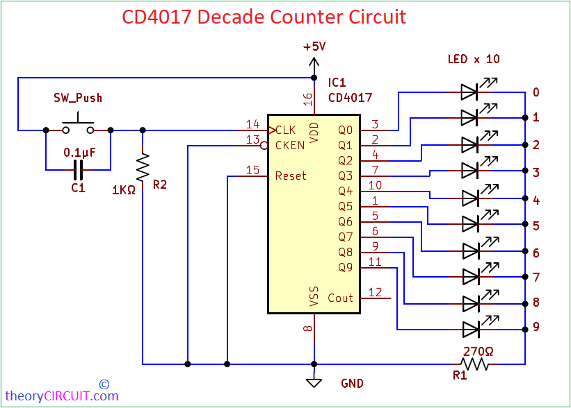
In digital Electronics counters are one of the most useful building blocks. We can build and…
Continue ReadingCategory: Digital
Digital Electronics Projects
Design Logic Gates using Transistors
Logic Gates are essential elements in digital circuit. For to perform logical operations on binary inputs…
Continue ReadingNOR and NAND Gates using transistor
When Someone ask what are Universal logic Gates? We immediately say NAND & NOR. This because…
Continue Reading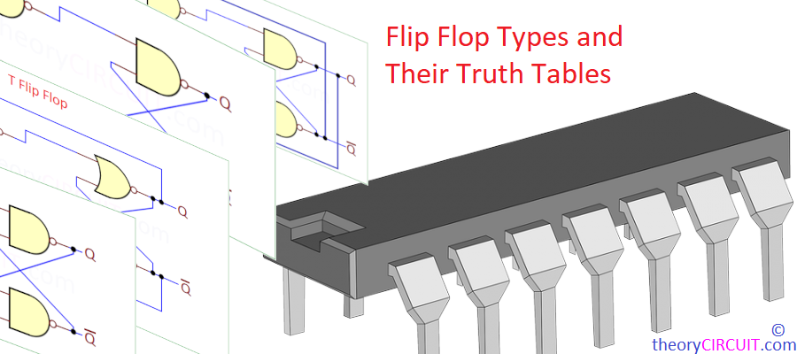
Flip Flop Types and Their Truth Tables
After learning about logic gates, next step is to know and learn about Flip-Flops, these are…
Continue ReadingSR Latch Circuit using Transistor
An SR Latch (Set – Reset) is a basic sequential logic circuit, that is commonly used…
Continue Reading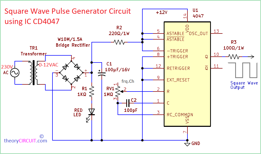
Square Wave Pulse Generator Circuit using IC CD4047
In Electronics R&D, prototyping and Hobby a Waveshpe plays important role that is Square Wave, to…
Continue Reading
Full Adder Circuit Diagram with Logic IC
The full adder circuit diagram add three binary bits and gives result as Sum, Carry out.…
Continue Reading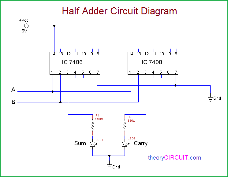
Half Adder Circuit Diagram with Logic IC
An Logic binary Adder circuit can add two or more binary bits and gives result as…
Continue Reading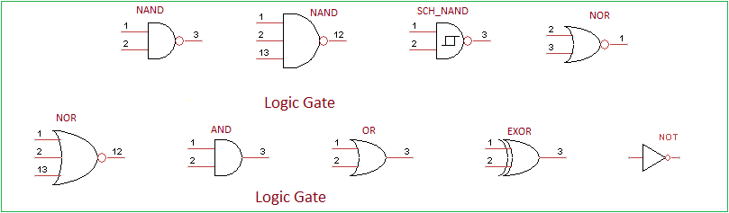
Basic Logic Gates Truth table
Electronic Logic Gates are used to implement Boolean functions practically. Electronic Logic Gates are comes in…
Continue Reading