Last Updated on September 8, 2025
In digital Electronics counters are one of the most useful building blocks. We can build and use counters depends on our needs. Here we are going to build decade counter circuit using IC CD4017. We know that CD4017 is a popular decade counter IC that comes with 10 decoded outputs from Q0 to Q9. When this IC receives clock pulse then it shifts its HIGH logic from one output to the next. This makes sequencing LEDs, Running chaser lights or even small scale counting applications.
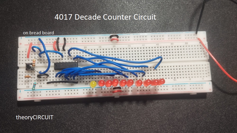
Here we are going to build simple CD4017 Decade counter circuit with 10 Output LEDs and a Push button to give manual clock when we press. So each press of a push button increases the count one by one then after completing all 10 steps (count), the counter circuit resets back to Q0 (first LED glows).
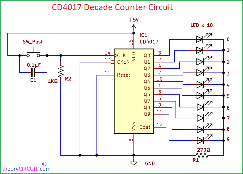
Circuit Diagram
Components Required
- IC CD4017 = 1
- LED = 1
- Push Button Switch = 1
- 0.1µF Capacitor (C1) = 1
- 1KΩ Resistor (R2) = 1
- 270Ω Resistors (R1) = 1
- DC Power supply +5V
Construction & Working
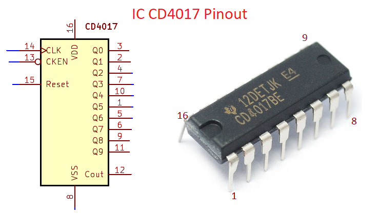
Here IC CD4017BE works as a Johnson counter, this IC has clock input (pin14) each HIGH pulse shifts the output, Reset (pin 15) forces the output back to Q0 when connected to HIGH or at the output pin Q. Clock enable (pin 13) is active low pin and allows counting when grounded and stops counting when connected to HIGH. Outputs Q0 to Q9 connected to LEDs.
Push button connected between +5V and CLK pin, R2 Resistor connected to CLK pin and GND. When the button pressed, it allows +5V to CLK pin as a clock input, so that IC CD4017 starts count one time. To solve bouncing effect from the push button we used 0.1μF Capacitor across push button.
This circuit works without external clock, it can be used as a manual counter and digit count related applications, we can extend the circuit by cascading another stage.