
Last Updated on March 16, 2024
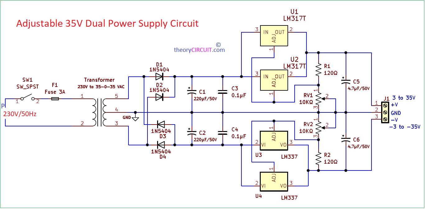
Adjustable 35V Dual Power Supply Circuit with 3 Amps output current range designed by using Positive Regulator LM317 and Negative Regulator LM337. This circuit gives output voltage from +3V to +35V and -3V to -35V. We know dual power supply circuit is essential in various electronic applications and projects, where a symmetrical and stable power source is required. Many operational amplifiers require dual power supplies to operate effectively, especially when dealing with signals that swing both above and below ground that is zero volts. Class B and Class AB audio amplifiers often utilize dual power supplies to drive both the positive and negative halves of the audio waveform, enabling better efficiency and performance. Circuits like analog filters, oscillators, and signal conditioners often benefit from a dual power supply to handle positive and negative voltage requirements. This circuit can be used as benchtop power supply for prototyping also.
In this circuit we have employed two LM317 Positive voltage regulators and two LM337 Negative voltage regulators in parallel to increase the output current capacity and share the load between the regulators, this type of connection will ensure better heat dissipation and better output efficiency and provides a stable and adjustable output voltage in this circuit. Maximum current output range of this circuit is 3A (3 Ampere). To implement this configuration, it’s crucial to ensure that both LM317 regulators and both LM337 regulators share an identical reference voltage. This is achieved by connecting their adjustment pins together. The output pins of the regulators are also connected together, forming a common output. However, each regulator maintains its own set of input and output capacitors for stability.
Circuit Diagram
Components Required
| 1 | C1, C2 | 220μF/50V | CP_Radial_D8.0mm_P3.80mm | 2 | ||
| 2 | C3, C4 | 0.1μF | C_Disc_D3.8mm_W2.6mm_P2.50mm | 2 | ||
| 3 | C5, C6 | 4.7μF/50V | CP_Radial_D6.3mm_P2.50mm | 2 | ||
| 4 | R1, R2 | 120Ω | R_Axial_DIN0411_L9.9mm_D3.6mm_P15.24mm_Horizontal | 2 | ||
| 5 | D1, D2, D3, D4 | 1N5404 | D_DO-201AD_P15.24mm_Horizontal | 4 | ||
| 6 | U1, U2 | LM317T | TO-220-3_Vertical | 2 | ||
| 7 | U3, U4 | LM337 | TO-220-3_Vertical | 2 | ||
| 8 | RV1, RV2 | 10KΩ | Potentiometer_Alps_RK163_Single_Horizontal | 2 | ||
| 9 | J1, J2 | Screw_Terminal_01x03 | TerminalBlock_Altech_AK300-3_P5.00mm | 2 |
Construction & Working
Operation of this 35 Volt Dual power supply circuit is simple and output can be Adjusted from 3V to 35V, First thing is Starts with Step down transformer, here 230V AC to 35V-0-35V AC stepdown transformer is used and output AC from secondary winding is Rectified into DC by using Bridge Rectifier made with Four 1N5404 Diodes, these are High Current and High Voltage General purpose diodes. Output rippled DC supply from bridge rectifier separated as Positive and Negative with respect to common Ground from secondary winding. Then C1 and C2 capacitors performs filter operations.
Two parallel Positive voltage Regulators LM317 and Two parallel Negative voltage Regulators LM337 makes Voltage Regulation depends on the feed back voltage dividers to the Adjust pin. There are two separate Voltage divider made and connected with Adjust pins of regulators. Final Regulated output DC in positive and negative side are filtered by C5 and C6 capacitors. Then output connector provides positive and negative adjustable output with common Ground. By varying the Value of RV1 and RV2 we can Adjust the output voltage level.
LM317 Pin Configuration
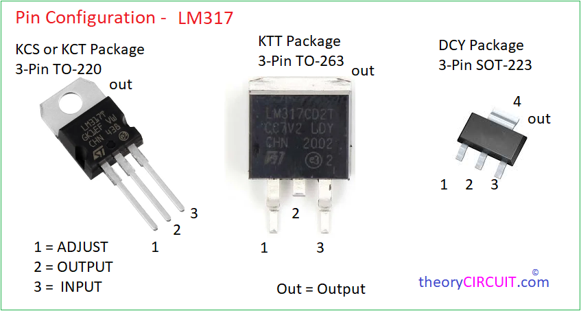
LM317 Pin Configuration

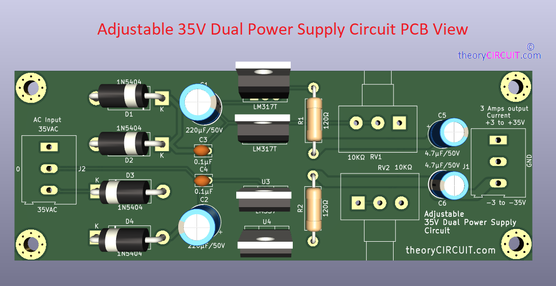
Printed Circuit Board
Adjustable 35V Dual Power Supply Circuit PCB Gerber File.
Interactive Board Viewer


PCB 3D View
Further