
Last Updated on April 27, 2024
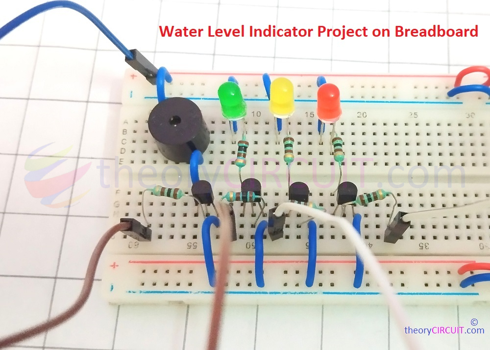
Making Electronics projects is a fun, learning and useful activity. Here is the best example, Simple Water Level Indicator Circuit with Buzzer. By making this project you can learn and understand about the conducting property of water and Characteristics of Transistor BC547 (NPN). This circuit is constructed by using only four Transistors and Indicator devices like Buzzer and LED. Let’s discuss about the problem, We often use water from storage tank for personal use, Gardening etc., to fill the water storage tank we use water pump motor and some times we forget about turned ON motor and hence Water overflow problem occurs often. In another case when we are in urge there will be no water on storage tank because we forget to turn ON the water pump motor so the water tank drained and empty. To avoid this awkward situation we don’t need High Cost water pump automation system. As an Electronics Maker we can bring simple solution by using Transistors.
We know that Transistor acts as switch, it conducts bias from collector to emitter when there is enough base supply. And the water conducts electricity with in specific range (water in small tank easily conducts small range power supply). So applying these two properties we can build simple and useful water level indicator.
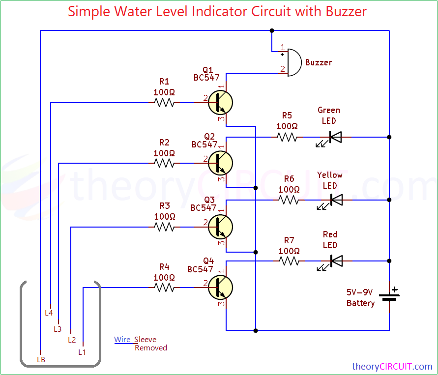
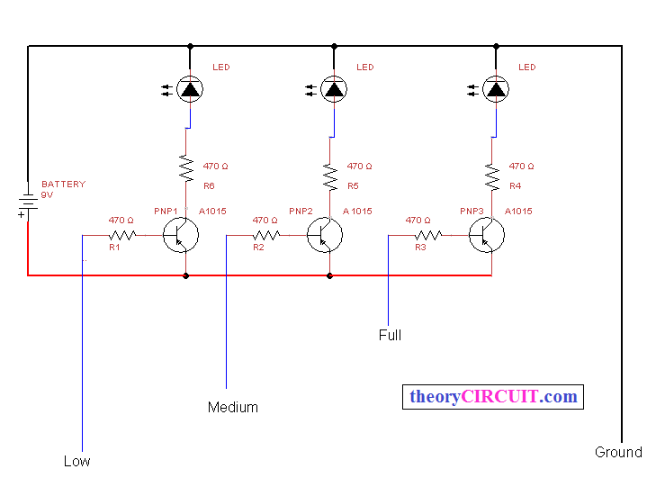
Water Level Indicator Circuit Diagram
Components Required for Water Level Indicator Circuit
- Transistor BC547 (NPN) = 4
- Buzzer = 1
- 5mm LED Red, Yellow, Green = Each one
- Resistor 100Ω = 7
- Connecting wires as required
- Battery 9V = 1
- Breadboard = 1

Working Video
Construction & Working
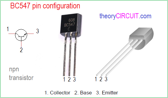
Before jump into construction and working details of this water level indicator circuit, let’s look into Transistor BC547, It is the main element of above circuit. BC547 comes in different package and we used TO-92 package device. It can operate in three regions called Cut Off, Saturation and Active. When the Collector terminal is biased with positive supply and Emitter terminal with Negative or GND. There will be no current flow due to zero base voltage and it stays in Cut OFF region. When we apply voltage above 0.7V in base then the Collector to Emitter current flow occurs and Transistor goes to saturation region. Here Cut OFF is equal to Open Switch and Saturation is equal to Closed Switch.
In Water Level Indicator circuit you can decide the measuring Points in the water tank to be Three, Four or more depends on your need, LB is Base Length wire and it is need to be placed possible bottom of the water tank and this will be used as positive supply terminal inside the water tank. Length 1 (L1) wire is connected to the base terminal of Q4 transistor through 100Ω Resistor, L2 wire to Q3, L3 wire to Q2 and L4 wire to Q1 transistor. Each length should cover ascending range of water tank level from base.
When the water fills the tank and reaches the LB wire first and make dc supply available in the water (tiny 9V DC battery supply do not harm), All transistor stays in open condition when there is no water touches the L wires. After some times the water level rise to L1 and makes Q4 transistor ON (Close) and makes Red LED glow, then water reaches L2 wire and makes Q3 ON and Yellow LED starts to glow, rising water level reaches the L3 and Transistor Q2 gets base supply through water and makes Green LED glow finally the water reaches the L4 wire and makes transistor Q1 ON and the buzzer connected with Q1 starts to make buzzer beep sound.
Improvements
This is model circuit and you can make improvements to this circuit by adding switch to turn off after water tank filled with water, you can use relay at the Q1 transistor.
Similar Circuits to Try
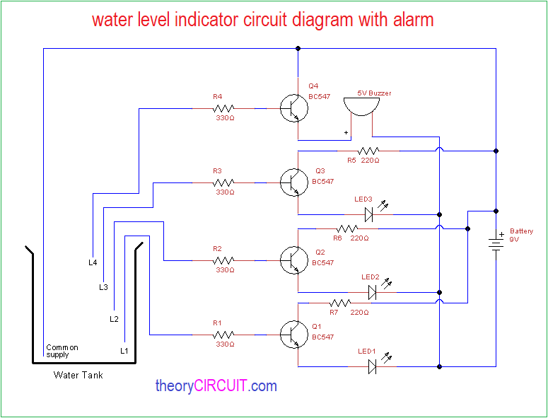
These circuits are do the same work, with some changes in circuit components and construction.