
Last Updated on July 7, 2024
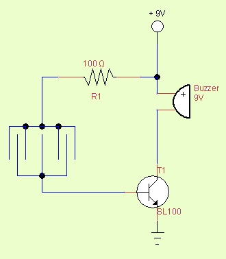
Single transistor Rain detector alarm or water drop detector alarm, We can use this circuit any way. This construction works under the principle of “transistor switch” when we giving voltage at the base terminal the transistor starts the conduction. When we remove the supply from base transistor goes to cutoff condition.
By using this character simple rain detector circuit made. By connecting buzzer series to the (npn) transistor we can get alarm circuit. The sensitivity range of this circuit varies with respect to the R1 resistor.
Handmade Rain Sensor
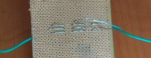
By using single stand wire and dotmatrix board we can make simple rain sensor, while making this sensor take two piece of wire remove the sleeve and stitch the metal into dotmatrix board without touching pair wire as mentioned in the circuit diagram.
Components List
| S.No | Name | Quantity |
| 1. | Transistor – SL100 | 1 |
| 2. | Buzzer 9V | 1 |
| 3. | Resistor 100Ω | 1 |
Simple Rain detector alarm circuit using BC547
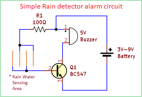
Instead of obsolete SL100 Transistor the above circuit uses commonly available BC547 NPN transistor in Rain detector circuit. The Rain Water Sensing area can be made with sleeveless conductive metal wires (either copper or single standard wire) use any non conductive base and sew wire without touching each others.
Working Video
Here the Transistor BC547 acts as switch and turn ON during rain drops falls on the sensing area then OFF when there is no rain.
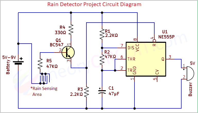
Rain Detector Circuit Diagram using IC 555
Required Components
- Timer IC 555
- Resistor 47KΩ and 2.2KΩ each 2
- Resistor 330Ω
- Electrolytic Capacitor 47µF
- Transistor BC547 NPN
- Buzzer 5V
- Single Stranded sleeveless wire
- DC power source 5V to 9V
This circuit will give give long time or adjustable time alert sound during rain. Here this circuit employed IC 555 timer in Astable Multivibrator mode with Reset control. Transistor Q1 allows Positive supply to reset pin during rain and makes 555 timer to functioning and Q1 Transistor becomes open when there is no rain and so the ground supply reach reset pin through R3 Resistor and keeps 555 timer in Reset (OFF) position, so there will be no sound.